Rube Goldberg Machine Calculations
Hi everyone and welcome back to the blog! This week we are moving on to possibly the most spectacular and satisfying project to date, namely the Rube Goldberg machine. I have watched these machines in action before on social media platforms and on tv advertisements for for viewer entertainment but apart from feeling a burst of dopamine I never wondered how they work. This was to change however as this week I will be documenting the build, careful calculations and considerations of making one of these machines myself.
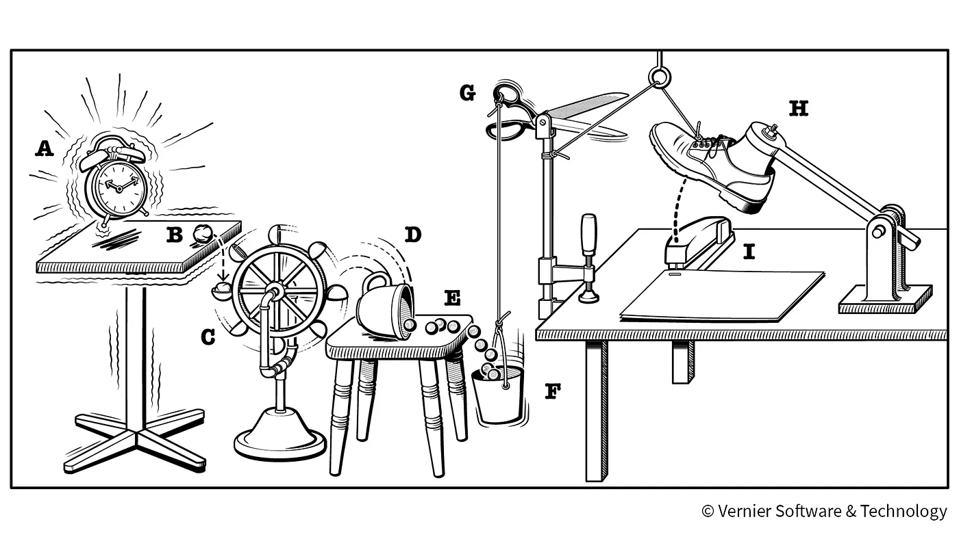
The key ingredient to making a great Rube Goldberg machine is to have a specific task which the machine has to complete. Most of the time this task isn’t complicated and can easily be done without the use of any tools/machinery, however in my eyes one of the main points of a Rube Goldberg machine is to entertain and therefore it should show an exhibition of mechanical prowess before completing a simple job. One of the first ideas that came to my head was to ‘use’ the Rube Goldberg machine as a kitchen appliance in making some food or drink. After debating on ideas such as making a sandwich, making coffee or a cocktail I decided to base the machine on making a cup of tea. I thought this was the best solution as in my functional demonstration I had plans to taste what my machine had made and I’m a big fan of tea and none of my other ideas. Finally to make concrete plans for this task I had to do a risk assessment on the use of boiling water in my project and how it can impact the safety of both myself and the robot. Will I able to drink this experimental cup of tea? Read on to find out!
During the construction of this machine I was also building my ping pong ball launcher at the same time. Therefore I decided it would be a great idea to incorporate the launcher into this project as well. As you will see from the video I used the first prototype of the launcher instead of the final design. This was because I wanted golf balls to be one of the key elements in my Rube Goldberg machine and the first prototype could fire golf balls flawlessly, whereas my final design was optimised for ping pong balls only. Due to the risk assessment concerning boiling water I had to stay 2 metres away from the machine at all times, therefore the use of the launcher to begin the chain reaction was a perfect match as I could fire the ball from a distance. I then proceeded to investigate the physics behind a projectile such as a golf ball being fired.

It is important to say that during these and future calculations I will be ignoring the effects of air resistance, friction and making reasonable and thought out assumptions and estimations. For this particular calculation I will place the launcher and target on the same horizontal plane, therefore I can ignore the effects of vertical displacement and only concentrate on horizontal range. To complete this calculation I will be using the projectile equation for a horizontal plane Sx=ucosθt. Where Sx is the displacement, u is the force the ball is launched at, θ is the angle of inclination of the launcher and t is the time elapsed since the launch. As the horizontal range was a constant of 2 metres in this example I needed to find u, θ and t for this equation. Luckily in my “Moving On To The Ping Pong Launcher” blog post I already calculated the force applied, velocity and acceleration of the ping pong ball in this launcher therefore my task now should be easier. Firstly the force applied was calculated to be approximately 0.8N. Next I wanted to solve time t, to do this I will estimate this value from the equation of motion s=ut+0.5at². By subbing in the values of 5.7m/s for velocity, 42m/s/s for acceleration and our fixed displacement, and then solving the quadratic equation for value t, I got an answer of -3.33 and 2.33 for the roots. We discount the negative answer as obviously time can’t be a negative value and the approximate time of the flight of the ball is 2.33 seconds which seems very reasonable. Next we sub the force of 0.8N and time of 2.33 seconds into the projectile equation for a horizontal plane and the angle of inclination of the launcher is to be approximately 41 degrees from the ground.

Another integral part of my Rube Goldberg machine would be the use of the Law of Conservation of Energy whereby the the net work done by all forces acting on a system equals its change in kinetic energy. In the first instance of this application I will use the force of the golf ball acting on a pulley system. I will use a simple fixed pulley system which will have 2 roles. Firstly one of the objects moving downwards which will act as a target for the golf ball will activate the kettle, and secondly the object moving upwards will push another golf ball into the next chain reaction. To compute the physics behind this I will use the work equation W=Fs first where W is the work done, F is the force applied and s is the displacement. A typical golf balls weight is 45 grams and I as it will be dropping down into the first target it will have an acceleration equal to the acceleration of gravity. The target will be a used tin of beans which weighs approximately 50 grams. Therefore the force will equal 0.93N and the tin will travel 1.5 metres downwards to the kettle. Finally the work is calculated to be equal to 1.39 Joules. From the law of conservation of energy we know that this is also equal to the kinetic energy, hence the second object in the pulley system must have a potential energy which is slightly smaller than 1.39 J. Next I calculated the mass needed for the potential energy to be 1.39 J using the formula P.E.=mgh. Since g and h are fixed with 9.81m/s/s and 2 metres above the ground respectively, I needed to find the mass of the second object. This mass equaled 70 grams, therefore I estimate that a mass of approximately 60 grams would work well in this pulley system and now I could draw my free body diagram.

I constructed enclosures for the kettle and the cup so that they can move in a controlled manner. My intention is for the cup to be slowly lowered down to the ground after which the kettle will pivot and pour hot water into it. The silver tube in which the wooden edge slides along will ensure that the cup is always at a perpendicular angle to the ground. Next I decided that pneumatics would be perfect in a task of gradually lowering down the cup as the gradual flow of fluid from one container to another would ensure this. Therefore I designed a sequence whereby a valve would be pulled open and water will flow from one container to another container located below. The second container will be attached to the cup enclosure by the use of a pulley system.

The cup enclosure with the cup inside has a mass of 380 grams and it is located 0.3 metres from the ground, giving it a potential energy of 1.1J. The weighted object would be placed 0.7 metres off the ground therefore it has to have a mass of at least 160 grams to be able to overcome the energy of the cup enclosure and be able to lower it down. The bottle would be located 0.5 metres off the ground and by calculating its potential energy similarly to above we know that its mass has to be at least 250 grams to be able to lift the weighted object. As water has a perfect 1kg/m³ density we know that at least 250 ml of water is needed for this pulley system to work. Therefore the bottle will have be either 500 ml or 700 ml capacity standard size. Next I decided to see how long it will take to pour 250 ml of fluid from one container to another and make sure it wasn’t too fast. I measured the flow rate out of the valve experimentally. I done this by attaching a 500 gram mass to the valve lever and dropping it with a 0.5 metre displacement. This opened the valve slightly and allowed a 1 litre container to fill to the brim in an average of 17 seconds. I repeated this experiment multiple times with a margin of error of 2 seconds. Finally the measured flow rate was 0.05 l/s which is a reasonably suitable flow rate in order to lower the bottle down slowly.

Finally I needed a part where I incorporate the robot into my machine. I decided that the robot will be used to rotate the kettle by 90 degrees, therefore pouring the water into the cup. To do this I attached a fishing line to the kettle enclosure and the robot wheel, the wheel will start turning, the line will get reeled in by the wheel and will thus pull the kettle enclosure. To complete this I wrote a piece of code which relies on the ultrasonic sensor and DC motor components. As can be seen from the picture above the robot is placed at an angle where the direct line of sight of the ultrasonic sensor illustrated by the red dashed line is pointing just above the weighted object. The working principal of this model is that the weighted object will move upwards, therefore triggering the ultrasonic sensor, when the ultrasonic sensor is triggers it will signal the DC motors to start rotating, thus pulling the kettle. The piece of code I wrote for this application can be seen below, whereby I initiated the DC motor and ultrasonic sensor in the void setup section then triggered both of them to work in the void loop.


I hope you enjoyed this weeks blog on the calculations and considerations I have while planning my Rube Goldberg machine. Please join me next week where I will be constructing the machine using all calculations above and then showing the final result. If you like the content posted on my channel consider following!
