
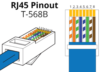
RJ45 (Registered Jack 45) is the connector that consists of 8 metal connection point. RJ45 pinout diagram shows the way how that connector provides communication with network devices. RJ45 exists at the end of the ethernet cables that is used for internetwork communication. There are T568A and T568B standards which are used for RJ45 cabling and these standards are known as RJ45 pinout diagram.
RJ45 Pinout For T568A Standard

RJ45 Pinout For T568B Standard
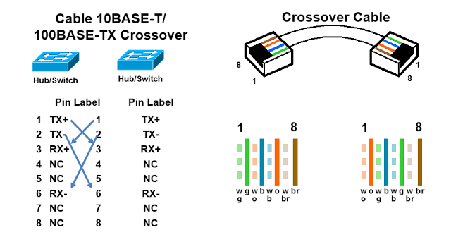
RJ45 Pinout For Crossover Cable
One thought on “RJ45 Pinout Diagram”
Absolutely super. I have one comment. The ethernet cables are not the first step in the chain of events, the first step is the female connectors in the different physical apparatus. How would it be if you started your explanation with the pinouts for the female connectors, showing the RJ45 female connector the two ways it can be, with the locking lug at the top and at the bottom, and with the pin numbers and functions for the two ways. Though even without this extra, your article is absolutely clear and concise. Many thanks, I’m going to get started crimping my RJ45’s.