Thyratrons
Thyratrons are a class of electron tube that are gas filled, and specifically made to switch either ON or Off. They have been replaced by modern thyristors, such as TRIACs and SCRs. They fall into two groups: (1) Cold cathode, often referred to as gas triggers, and (2) hot cathode, just referred to as thyratrons.
Hot Cathode Thyratrons:


Above is a sampling of small to medium sized thyratrons. These can pass significantly more current than vacuum tubes, but the larger ones require significant filament power. Below is a table of specifications:

Unlike TRIACs, thyratrons can only conduct in one direction, and act more like SCRs. One of the key limiting specifications is plate current, where both Peak and Average values are given. For devices intended for continuous current flow, as opposed to pulse operation, the peak value is usually not more than 10x the average rating. The following is a table of loads that can be driven by common thyratrons:

On the right are nominal power values, if the load (such as a light bulb) was hooked up directly to a full wave AC source. Its nominal Hot resistance is determined, and entered on the table. Note: this is the Hot resistance, and will be several times what is measured with an ohmmeter. This represents the true load, when the load, is operating at a raised temperature. From that resistance the peak current, and therefore the average current (1/pi of the peak), can be determined. In the comment field, either the part number of a specific thyratron, or the load type, is given.
Thyratron Color Organ
The tube circuit, that made a bad example, that carried on to the state solid circuits in the 60’s and 70’s. No TRUE phase control ! And all this time I’d been blaming it on the Hippies ! (Click on magazine cover to download PDF article – 1.7MB):

The circuit, in the article, above, makes a half hearted attempt at phase control. The thyratrons used are directly heated, and the AC fluctuation filament windings, are used for rough phasing. The problem is that only works for a quarter of the wave. plus the transformers used, are underated, and deliver inadequate current, which you should never do with thyratrons. Especially, with thyratrons passing a significant amount of power.
A Proper Color Organ Circuit:

(Click on drawing, above, to enlarge)
This circuit works similarly, to those I designed for modern TRIACs. The AC line is used to generate a synchronized ramp pulse, which rises continuously, during the entire active half wave, where the thyratron may switch ON. The earlier in the wave, the brighter, the driven lamp load. This ramp is compared to the audio signals “envelope”. The V2B triode stage, is hooked up as a voltage comparator. When the audio signal (VA) is driven more negative than the ramp (VR), V2B, will turn OFF, and its plate voltage will go positive. This will turn ON the thyratron. V2B is ON most of the time, presenting a negative voltage to the thyratrons control grid, keeping it OFF. The louder the audio, the more negative, will VA be, it will cross VR earlier, in time, increasing the thyratons ON time.
Auxiliary info, for multiple channels and power supply. (click on drawing to enlarge):

This proves, that a proper color organ circuit could have been made, well inside the tube era. The tubes, used in this circuit, are all miniatures, which first came out in 1940. But thyratrons came into existence early in the tube era, so this circuit could have been made as early as the late 20’s.
(Click on drawing, below, to see video of the circuit in action):

Unlike modern thyristors, hot cathode thyratrons have very sensitive grid triggers. Known as critical grid current, its a very low value. Typically under 1 uA, and rarely over 10uA. SCRs usually need a few 100uAs, and TRIACs, 3mA at the low end, and 50mA being quite common. That means, this circuit, can be used with just about any thyratron. Even a big 5559 ! Only adequate filament power needs to be addressed.
Complete 3-Chl Color Organ:
(click on photo, below, to view video):

Here’s a completed 3 channel color organ, using only tubes, with thyratrons lighting the incandescent lamps. The circuit uses a simplified phase circuit, which can be used with most thyratrons that have indirectly heated cathodes.
Below is the schematic (click on drawing to enlarge):

Note it uses small 5663 thyratrons which have 150mA (6.3V) filaments. This allows me to use a series heater string, current limited by the reactance of film capacitors, off the 120VAC (60Hz). The 5663 tubes, though, only allow for lamps, no bigger, than 5W. It can be upgraded to use the 2D21, or even 6012 tubes. Both of these types have their cathodes split from their filaments (indirectly heated). But if these larger tubes are used, then its better to use a separate filament transformer (of proper capacity), in place of the heater string.
The circuit uses two 6BC7 triple diodes, which are the same diodes used in your common 6AL5, but there’s 3 instead of two, and the heater demand goes up accordingly (450mA vs 300mA). One 6BC7 (V4) is used for power rectification (+90V, & -90V), plus part of the ramp generator circuit. The other 6BC7 (V6) sections are used for each of the 3 envelope detectors. A 6EZ8 triple triode is also used. One triode section per channel, for basic amplification. The 6EZ8 has the odd “feature” of having two of the triodes’ cathodes tied to a filament lead. This means that ,that lead (pin 4), must be tied to circuit common. This means cathode biasing is not possible, and a small negative bias must be provided to the grids (C-, ~-1.5V). A 6BQ7 dual triode (V5) finishes up the tube set, which is used for the ramp generator.
Below, is the drawing explaining the simplified phase control. Thyratrons are usually triggered if the grid voltage goes a tad more positive than some negative threshold voltage. For the tubes used, at the given supply voltage, its around -2V. The audio envelope and ramp are simply summed with two equal value resistors. 2.2M in this case, for each channel. The resulting grid voltage is the average of these two signals. This is already half the amplitude as the older, more complex phase control circuit. Plus the audio signal is further reduced, due to the use of the 6EZ8, which must have its cathodes tied to common. If a triode with independent cathodes are used the circuit could be cathode biased, and also use the -90V, doubling the maximum audio envelope level.
It does work quite nicely, though, within the limitations, noted.
If you want to make your own, here is a template of the “board” layout.
(Click on drawing to enlarge):

This layout drawn to scale. If printed at 200DPI, the printout will be actual size. I overlayed it onto a 6.5″ x 6.5″ piece of acrylic, and used a center punch (actually a drywall screw) to transfer the hole positions onto the acrylic sheet. Then drilled the holes to the appropriate sizes. Green wires are on the component side (same side as the components), and red wires are on the solder side (opposite side). Purple wires are also on the solder side, but require insulation. Insulation optional, but recommended for other wires.
There are also 6 resistors (3 referenced RH and 3 RK), that are not shown in the schematic. These are optional, and only used here, because the lamps used are actually listed as 7W, but actually measure 5.5W. Those resistors limit the current to below 5W, per bulb.
Modifications, to change fixed biased to self biased:
(Click on drawing to enlarge):

Fixed biasing didn’t sit well with me. It works, but as the 6EZ8 tube ages, this point will drift. Also a replacement tube may not set at the same bias point. If Fixed bias is used a trimpot really needs to be installed, so C- can be adjusted. But I don’t like using trimpots, if I don’t have to. One way to do this is to change to self biasing. Its a shot gun approach, and can be used with just about any triode, indifferent to its amplification factor.
Well almost any. If you look at the drawing, the component values chosen set the bias point of VA close to its ideal location, at about 1/2 of B+. It will be short, roughly 2x VG. The higher the transconductance, the smaller VG will be. On a NOS 6EZ8 its only -1V, but that’s my batch of 6EZ8s. It could be different from different batches. Even from the same manufacturer.
I come from a commercial electronics (not necessarily consumer, but its a subset) design background. No parts batching. No coercing the parts makers to use an old process, because you’re a heavy (old HP & Tektronix). Do a design that involving instrument makers methods, and you’ll find yourself transferred to sales. Design so that just about any part will work !
Sweep Generator Application:
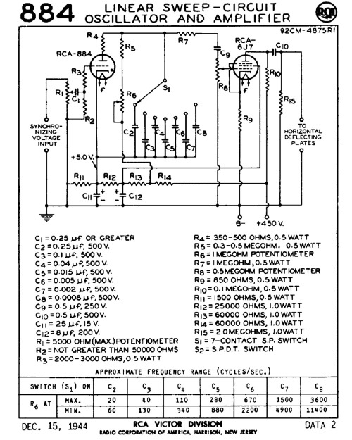
Note, in the organ app, above, a common triode was used to generate sawtooth ramp waveform. In the tube era, however, thyratrons were used for this purpose. Especially, in oscilloscopes. Thyratrons like the 2.5V 2B4/885/128A, and 6V 6Q5/884. Below is the typical sweep circuit from an RCA 884 datasheet:
(click on drawing to view demo circuit, in action):
Here is a demo circuit, that trips a thyratron with a simple neon relax oscillator:
(click on drawing to enlarge)

This demo circuit is powered from a 12V supply, and draws a tad over 1/2 amp. A royer oscillator is used to primarily generate the filament voltage, and oscillates at near 50KHz. The primary has a bit of inductive “kit”, an that’s pumped thru a multiplier ladder to generate ~55V for the thyratron anode supply, and ~140V for the neon relax oscillator.
The demo tube (V1) has its cathode biased up to +6V. This makes the grid nominally rest -6V below the cathode. When the neon flashes, the current spikes the grid voltage positive, and initiate ionization. C14 then dumps its current thru the tube causing a flash, and pull the anode voltage low. Once, below ionization voltage, conduction extinguishes, and C14 ramps up again, waiting for the next grid pulse, and repeat the process.

(Click on photo, above, to enlarge):
Dinky Thyratrons:
Thyratrons come in all sizes. Not all, are large devices for driving heavy loads. Some a quite small, intended to pass just enough current to drive a small relay, or some odd application, such a noise generator (6D4). Here’s a photo of a view:
(Click on photo to enlarge):

The 5663 and 6D4 can drive currently available general purpose relays. Many draw a tad less than 20mA. The Raytheon RK61 is an odd ball. Its intended to be battery powered, and can only drive a 1.5mA load, maximum. There use to be completely electromechanical relays, in the past, that could be engaged by such a low current. In the modern era, due to semiconductors, the need for such devices are no longer needed, since its child’s play in silicon.
Simple Phototube Demo Circuit:
Here’s a demo circuit that uses a phototube and a small thyratron, to switch a relay. This simple circuit was included as a sample app, for small RCA thyratrons like the 5727 (premium 2D21) and the 5696. Its drawn a little different here, buts its almost exactly the same circuit as shown in the datasheets, for the two tube types, above. Here is the circuit using a Cetron B-25 (Red, gas) phototube, and a 5663 thyratron. The 5663 specs similar to the RCA 5696, and even closer to the GE GL-546. Even has the same pinout as the GE tube:

The only difference between the drawing, above, and the datasheet circuits, are that the values are given here, and that the filament is shown being powered thru a 3.3uf film, current limiting cap. Also the load is an Omron G5LE-14 24V relay. The coil voltage is really unimportant. What matters, is that the current draw, to engage the relay, is less than the 20mA max average, that the 5663 can handle. In the circuit, I built, it was drawing ~15mA.
When Operating this circuit, apply the 120VAC, with S1 “OFF”. Keep it OFF, for at least 30 seconds. The filament is not switched, so this allows the cathode to heat up, and form the electron cloud around it. Once warmed up, then S1 can be closed (turned ON), and present plate voltage. Note that there are no rectifiers, and that this circuit works on mostly AC. The plate circuit, does rectify the current going in the relay, and the 47uf cap, filters it into steady DC, going thru the relay coil. Don’t do the “capacitor trick”, for current limiting, other than in the heater circuit. Current limiting using caps, works by shifting the phase between voltage and current. In thyratron circuits, that can wreak havoc. S2 just selects which contact is connected to the lamp load (NC or NO).
Here’s a video of the circuit:
Here’s data on the GE 5663:
Below is the original circuit from the RCA datasheet:

The resistors R1, R2, & R3 correspond between the two drawings. This snippet, is out of both the datasheet for the 5727 and 5696. Since, I’m using a gas phototube, instead of a vacuum type, I tap in the middle of “R2”, so the voltage rating of that tube is not exceeded.
No data found on the Cetron B25. From the coating on the cathode, its response is towards the red side (~800nm). If I hit it with an IR source, in the dark, and see it slightly glowing, then its a gas phototube. Care must be taken with these. They are more sensitive, than vacuum phototubes, but should never be exposed to more than 90V peak !
Cold Cathode Thyratrons – (aka Gas Triggers):
Krytron Cold Cathode Arc Trigger Tubes
Krytrons are specialized high current cold cathode gas trigger tubes that work in similar fashion to the 0A5 tube. This group of tubes claim to fame, is due to their use in detonating the chemical explosives, that initiate the nuclear explosion, of an implosion type atom bomb. These tubes were (or still are) not allowed to be exported. Several model numbers made by EG&G Corporation. Here are some photos (click on photos to enlarge):


End.

You must be logged in to post a comment.