DETERMINATION OF PILE CAP DEPTH
Dr.Subramanian, Ph.D., FNAE, F.ASCE, M.ACI Narayanan
I received the following question from a senior Structural Engineer from India.
I have a doubt regarding assuming pile cap thickness. There are two theories Beam theory and truss theory. In truss theory, the empirical formula for pile cap depth, when the pile diameter less than 550mm is,
D= 2 × dp+100 mm , Where D is the pile cap depth and dp is the pile diameter
Thus, if pile diameter is 450 mm, D= 2× 450 + 100=1000mm.
However, when the pile diameter is greater than 550mm, the empirical formula is
D = 1/3(8dp+600)
Thus, when the diameter of the pile is 600mm, D= 1/3(8 × 600+600) =1800mm.
In beam theory, the minimum thickness is 600mm
The thickness is based on bending, one-way shear, and two-way consideration. Er. Varyani sir has given one formula in his book, for finding the thickness of a pile cap. But he considers a pedestal of 300mm around the column and has given the following equation
a/2 + 300 + Deff/2= S/2 + dp/2.
Where a is column width, D is the effective depth of pile cap, S is the spacing of piles, and dp is pile diameter.
For a 450mm diameter of the pile with a column width of 450 mm and a Spacing of piles of 1350 mm,
Deff = 750mm
D=750 plus cover+ diameter/2 say 100.
D=850 say 900mm.
My doubt is beam theory requires less depth. For finding thickness in beam theory is there any empirical formula available? Kindly inform me. Thank you.
My Reply is as below:
Thank you for your message. Yes. There are two theories of designing pile caps. One is by bending theory, as advocated in IS code, and the other is the Strut-and-Tie theory, first developed by Prof. Schlaich and others in their paper(1987) and adopted by ACI 318 (same as the Truss theory as mentioned by you). Many researchers [Adebar et al. (1990); Adebar and Zhou (1996) Bloodworth et al., ( 2003); Cavers and Fenton (2004); Park et al., (2008)] concluded that pile caps that were designed by the bending theory are found to fail in a brittle mode due to shear. Adebar and Zhou (1996) compared their previously suggested model with testing 48 pile caps. They concluded that the ACI 318-83 provisions for one-way shear design are extremely conservative and that the conventional procedures of flexure design for two-way slabs and beams are unconservative for pile caps
The formulae for pile cap thickness, based on pile diameter have been derived from experience, rather than any theory and were first mentioned in Reynolds Handbook (1988). Prof. Varghese, in his book, mentioned that if the angle of dispersion of load theta is less than 30 degrees or av/d is less than 0.6( where av is the distance from the centerline of load to the centerline of the pile, we can consider strut action. But in the same book in the next line, he says that experiments show that this action may be predominant up to av=2d (No references are mentioned), meaning for most of the pile caps, the strut-and-tie method (STM) may be valid. STM states that the tensile forces are carried by steel reinforcement in the tie region and the compressive forces are carried by concrete compressive struts. These struts and ties should transfer the applied forces from the column to the piles.
Anyway, Reynolds Handbook (1988) also mentions that the minimum depth of a pile cap should not be less than 600 mm. Hence, even if the depth calculated as per bending theory is less than 600, you should adopt a minimum thickness of 600 mm.
I believe that Er. Varyani in his book has assumed a 45-degree dispersion of load at the center of the pile cap and arrived at the formula for the depth of the pile cap.
Several codes of practice such as the American Concrete Institute (ACI 318) code, the Canadian Standards Association (CSA), the Australian Standard, and the New Zealand Standard are now suggesting the strut-and-tie method as an appropriate and alternative design procedure for pile caps. Shear verification is highly recommended by many researchers when designing pile caps although it is not recommended in these codes when designing by the strut-and-tie method. The researchers attribute the shear failure in pile caps to the longitudinal splitting of the compression struts. Hence, a shear span/depth ratio under 1.0 and compressive stress under 1.0f’c is suggested to result in ductile failures. In the ACI Building Code, the minimum angle between a strut and a tie joining at a node is set to 25°.
Reinforcement as per These Theories
As per the bending theory, the pile cap reinforcement is placed at the bottom of the pile cap, similarly to a two-way slab, with reinforcements spread over the entire pile cap.
As per the strut-and-tie method, reinforcement should be provided connecting the piles. Since tension ties have constant force in them, they should be anchored for the full horizontal tie force outside the intersection of the pile and the compression strut. hence, the bars either must extend a distance equal to Ld past the center lines of the piles or must be bent with a 90-degree hook, if the distance beyond the centerline of the pile is not sufficient to provide Ld. In addition, some minimum steel is provided in the center of the pile cap as shrinkage reinforcement.
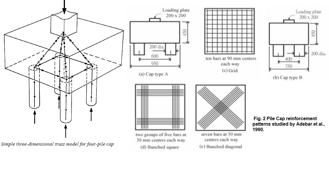
Blévot and Frémy (1967) conducted several tests on about 100 pile caps. They showed that spreading flexural reinforcement uniformly over the bottom of the pile cap, instead of using square bunched (concentrated) reinforcement over the supports, reduced on average the failure load by 20% for four pile caps and by 50% for three pile caps. In 1973, Clarke (1973) arrived at a similar conclusion with an average increase of the ultimate load by 15% when using square bunched reinforcement on four pile caps compared to the smeared arrangement. It was also shown by Blévot and Frémy (1967) that using square-bunched reinforcement resulted in a higher capacity than using cross-bunched reinforcement, see Figure 2. They also showed that cross-bunched reinforcement did not provide better ultimate capacity than grid reinforcement.
More details on the design using the strut-and-tie method of design are provided in the ACI 318-19 code and Nori and Tharval (2007) and an example of a pile cap supporting 4-piles is provided in my book (Subramanian, 2013)
References
- Adebar P, Kuchma D and Collins M P (1990), “Strut-and-Tie Models for the Design of Pile Caps: An Experimental Study”, ACI- Structural Journal, Vol. 87, No. 1, pp. 81-92.
- Adebar P and Zhou Z (1996), “Design of Deep Pile Caps by Strut-andTie Models”, ACI-Structural Journal, Vol. 93, No. 4, pp. 1-12.
- ACI-318 Committee, American Concrete Institute (2019), “Building Code Requirements for Structural Concrete (ACI 318-19) and Commentary (318R-19)”, Michigan
- Blévot, J. L., and Frémy, R. (1967) “Semelles sur Pieux,” Institute Technique du Bâtiment et des Travaux Publics, V. 20, No. 230, 1967, pp. 223-295.
- Bloodworth A G, Jackson P A and Lee M M K (2003), “Strength of Reinforced Concrete Pile Caps”, Proceedings of the Institution of Civil Eng., Structures and Buildings, Vol. 156, No. SB 4, pp. 347-358.
- Canadian Standards Association (1994), “CSA Standard-A23.3-94—Design of Concrete Structures”, Canada.
- Cavers W and Fenton G A (2004) “An Evaluation of Pile Cap Design Methods in Accordance with the Canadian Design Standard,” Canadian Journal of Civil Eng., Vol. 31, No.1, pp. 109-119.
- Clarke, J. L. (1973) Behavior and Design of Pile Caps with Four Piles, Technical Report No. 42.489, Cement and Concrete Association, Wexham Springs, 1973.
- Nori V V and Tharval M S (2007), “Design of Pile Caps—Strut and Tie Method”, Indian Concrete Journal, Vol. 81, No. 4, pp. 13-19.
- Park, J., Kuchma, D.A., and Souza, R.A. (2008) “Strength Predictions of Pile Caps by a Strut-and-Tie Model Approach”, Canadian Journal of Civil Eng., Vol. 35, No. 12, pp. 1399-1413.
- Reynolds, C.E., and Steedman, J.C.(1988) Reinforced Concrete Designer’s Handbook, E & FN Spon, London, 436 pp.
- Schlaich, J., Schaefer, K., and Jennewein, M.(1987) “Toward a Consistent Design of Structural Concrete”, PCI Journal, Vol. 32, No.3, pp. 74-150.
- Subramanian, N. (2013) Design of RC Structures, Oxford University Press, New Delhi, 856 pp.
- Varghese P.C. (2009), Design of RC Foundations, PHI Learning Pvt. Ltd., New Delhi, pp. 240-243.
Bridge design engineer.eager to learn.intrest in reading and teaching.Team leader...
1yThank you sir
Structural Engineer || Project Manager || passionate about the construction industry
1yOkay…
Imagination Realized
1yIn one of my projects, i used beam theory for my pile cap. For practical purposes, i opted to only allow concrete shear strength to govern. Since pile caps are short elements, it is understandable that shear always governs, hence the depth of the pile cap. As for the flexural requirements, always follow what is needed by the code. That includes development lengths and flexural capacity.
L. K. JAIN Associates, Consuting Group
1yDear sir, you have given a good account of the pile-cap design. The safety for shear controls the depth of the cap. Usually, the span is small and simple beam theory is not applicable in most pile caps. Hence the truss analogy is advocated. The main difference in the 'truss-analogy' approach is the full anchorage of tension bars beyond each support i.e. the piles. This anchorage of bars will control the failure. Hence recommendation is that tension bars must be provided with 'L' hook (90 degree hook) at the end with a corner bar at the bend (hook). For 400 diameter piles, I have designed caps 550 thick for water tanks. Gravity loads are not heavy (as for buildings), and bending of the pile for horizontal loads controls the size of the pile and not the end bearing consideration.