Radar Cross-Section (RCS)
Radar cross section (RCS) RCS is specified as a multiple of a perfectly conducting sphere with a diameter of 1.128 m. The sphere has a visible surface of 1 m², but only a small effective area for backscatter. Therefore, better reflecting surfaces can have much larger RCS than their geometric dimensions.


The Radar Cross Section (RCS) is a measure of a target's ability to reflect radar signals in the direction of the radar receiver. The RCS of a target is equal to the ratio of the power reflected by the target in the direction of the radar receiving antenna (per unit solid angle) to the power density incident on the target (per square meter).
Some characteristics of the target's Radar Cross Section can be described using simple models, dividing the RCS into three regions based on the relative relationship between the radar wavelength and the target size.

Rayleigh Region: In this region, the target size is significantly smaller than the signal wavelength. The Radar Cross Section (RCS) of the target is not strongly influenced by the radar observation angle and is directly proportional to the fourth power of the radar frequency.
Resonance or Mie Region: In this region, the wavelength is comparable to the target size. The RCS of the target varies with frequency, with a range of up to 10 dB. Additionally, due to the discontinuity in the target shape, the RCS changes with variations in the radar observation angle.
Optical Region: In this region, the target size is larger than the signal wavelength, typically exceeding the upper limit of target sizes in the Rayleigh region by an order of magnitude. The RCS of simple-shaped targets can approximate their optical cross-section. Changes in the line of sight angle, caused by the movement of the target or radar, result in variations in the RCS of the target.
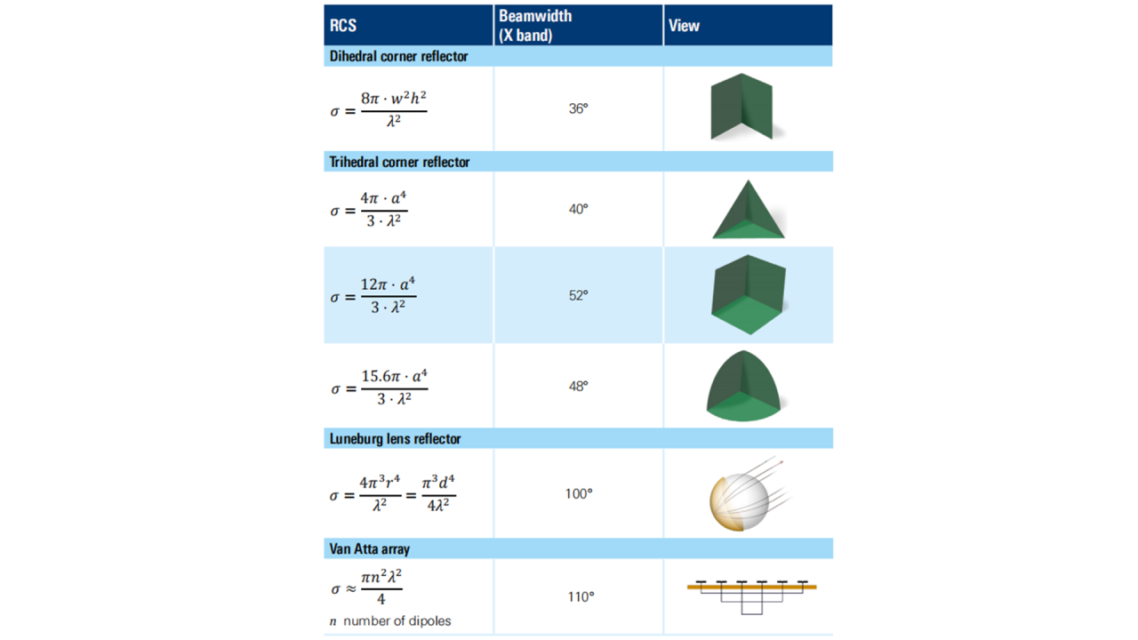
RCS Calculation of Corner Reflector
Besides the simple targets in Figure 3, whose RCS can be calculated by formulas, some regular-shaped corner reflectors can also calculate their RCS, as shown in the following table:

The interaction of complex targets with electromagnetic waves includes specular reflection, edge diffraction, apex diffraction, creeping wave diffraction, traveling wave diffraction, and diffraction caused by electromagnetic discontinuity in non-slender bodies. For conventional aircraft, its scattering field comprises both reflection and diffraction fields, primarily governed by specular reflection and edge diffraction.

The use of RCS evaluation and calculation methods requires attention to the size range within which to analyze. The accurate method is based on the integral and differential forms of a Maxwell's equation group, generally limited to relatively simple and small objects in the Rayleigh region and the resonance region, while most approximate methods are developed for the optical region.
RCS Values for Complex Targets
The RCS of relatively complex targets can be estimated using various approximation methods. For example:
Geometric Optics (GO): Assumes rays propagate in straight lines, utilizing classical ray path theory.
Physical Optics (PO): Applies the approximation of planar tangents and calculates RCS through Huygens' principle.
Geometric Theory of Diffraction (GTD): A synthetic system that integrates concepts from both GO and diffraction lines.
The RCS can be obtained by experimental measurement or computer modeling, but it requires detailed information of the target, and a large amount of data needs to be generated according to the radar working frequency and the radar observation angle.
The following presents the RCS value range for various targets in the X-band:

X Band Luneberg Lens Passive Radar Reflector: