Table of Contents
Advertisement
Quick Links
Advertisement
Table of Contents

Related Manuals for Asus Maximus VII Formula Series


Summary of Contents for Asus Maximus VII Formula Series
- Page 1 MAXIMUS VII FORMULA Series...
- Page 2 Product warranty or service will not be extended if: (1) the product is repaired, modified or altered, unless such repair, modification of alteration is authorized in writing by ASUS; or (2) the serial number of the product is defaced or missing.
-
Page 3: Table Of Contents
Contents Safety information ..................... vii About this guide ....................... viii MAXIMUS VII FORMULA Series specifications summary ........x Package contents ...................... xv Installation tools and components ................. xvi Chapter 1: Product Introduction Special features..................1-1 1.1.1 Product highlights................ 1-1 1.1.2 ROG Gaming Features ............... - Page 4 3.6.10 ROG Effects ................3-43 Monitor menu ................... 3-44 Boot menu ....................3-47 Tool menu ....................3-53 3.9.1 ASUS EZ Flash 2 Utility ............3-53 3.9.2 ROG Secure Erase ..............3-53 3.9.3 Graphics Card Information ............3-54 3.9.4 ASUS Overclocking Profile ............3-55 3.9.5...
- Page 5 Sonic SenseAmp..................4-37 Sonic SoundStage ..................4-39 DTS Connect....................4-40 Sonic Radar II ................... 4-41 GameFirst III ..................... 4-43 KeyBot....................... 4-46 4.10 ASUS Media Streamer ................4-48 4.11 ASUS Disk Unlocker ................4-50 4.12 RAMDisk ....................4-51 4.13 MemTweakIt ....................4-54 4.14...
- Page 6 Creating a RAID driver disk without entering the OS ....5-7 5.2.2 Creating a RAID driver disk in Windows ........5-8 ® 5.2.3 Installing the RAID driver during Windows OS installation ..5-8 ® Appendices Notices ........................A-1 ASUS contact information ..................A-4...
-
Page 7: Safety Information
Safety information Electrical safety • To prevent electrical shock hazard, disconnect the power cable from the electrical outlet before relocating the system. • When adding or removing devices to or from the system, ensure that the power cables for the devices are unplugged before the signal cables are connected. If possible, disconnect all power cables from the existing system before you add a device. -
Page 8: About This Guide
Refer to the following sources for additional information and for product and software updates. ASUS website The ASUS website (www.asus.com) provides updated information on ASUS hardware and software products. Optional documentation Your product package may include optional documentation, such as warranty flyers, that may have been added by your dealer. -
Page 9: Conventions Used In This Guide
Conventions used in this guide To ensure that you perform certain tasks properly, take note of the following symbols used throughout this manual. DANGER/WARNING: Information to prevent injury to yourself when trying to complete a task. CAUTION: Information to prevent damage to the components when trying to complete a task IMPORTANT: Instructions that you MUST follow to complete a task. -
Page 10: Maximus Vii Formula Series Specifications Summary
MAXIMUS VII FORMULA Series specifications summary Intel LGA1150 socket for the 5th, New 4th, and 4th Generation ® Intel Core™ i7/ i5/ i3/Pentium /Celeron Processors ® ® ® Support 22nm CPU Support Intel Turbo Boost Technology 2.0* ® * The Intel Turbo Boost Technology 2.0 support depends on the CPU... - Page 11 MAXIMUS VII FORMULA Series specifications summary Intel Z97 Express Chipset ® 1 x SATA Express port (red at bottom, compatible with 2 x SATA 6.0 Gb/s ports) 1 x M.2 Socket 3 with M Key, type 2260 storage devices support (both SATA &...
- Page 12 ® 2 x USB 3.0 ports (at back panel [blue]) * Support ASUS USB 3.0 Boost, UASP standard on the Intel native USB 3.0 is only supported under Windows® 8.1/8. ** 2 x USB 2.0 port at mid-board shares with ROG extension (ROG_EXT) port.
- Page 13 - MemOK! ASUS Q-Design - ASUS Q-Code - ASUS Q-Shield - ASUS Q-Connector - ASUS Q-LED (CPU, DRAM, VGA, Boot Device LED) - ASUS Q-Slot - ASUS Q-DIMM 1 x Clear CMOS button 1 x ROG Connect On/Off switch 1 x PS/2 keyboard/mouse combo port 2 x USB 2.0 ports (upper port for KeyBot, bottom port for ROG...
- Page 14 1 x MemOK! button 1 x KeyBot button 1 x Sonic SoundStage button 1 x Front panel audio connector (AAFP) 1 x Thunderbolt header (5-pin) for ASUS ThunderboltEX series support 1 x TPM connector 1 x System panel connector 1 x mPCIe Combo III connector 64Mb UEFI AMI BIOS, PnP, DMI2.7, WfM2.0, SM BIOS 2.8,...
-
Page 15: Package Contents
1 x SLI™ cable 1 x I/O Shield 1 x mPCIe Combo III card with dual band Wi-Fi 802.11a/b/ g/n/ac + Bluetooth v4.0 1 x ASUS 2T2R dual band Wi-Fi moving antennas (Wi-Fi 802.11a/b/g/n/ac compliant) Accessories 1 x 2-in-1 Q-Connector Kit... -
Page 16: Installation Tools And Components
Installation tools and components 1 bag of screws Philips (cross) screwdriver PC chassis Power supply unit Intel LGA 1150 CPU Intel LGA 1150 compatible CPU Fan DDR3 DIMM SATA hard disk drive SATA optical disc drive (optional) Graphics card (optional) The tools and components in the table above are not included in the motherboard package. -
Page 17: Chapter 1: Product Introduction
This motherboard features a unique PCIe 3.0 bridge chip to support multi-GPU SLI ® ™ CrossFireX graphics cards for an unrivalled gaming performance. With the Intel ® platform to optimize the PCIe allocation of multiple GPUs, it supports up to 2-WAY SLI ® ™ 3-Way CrossFireX configuration. ASUS MAXIMUS VII FORMULA... -
Page 18: Rog Gaming Features
GameFirst III ASUS GameFirst III is a network management software that features four preset packet prioritized profiles (Optimization, Game, Media Streaming and File Sharing) facilitating user’s need. Users can also manually allocate bandwidth and adjust priority settings of each application to run faster and smoother. -
Page 19: Rog Exclusive Features
ASUS Special Features AI Suite 3 With its user-friendly interface, ASUS AI Suite 3 consolidates all the exclusive ASUS features into one simple-to-use software package. It allows you to supervise fan speed control, voltage and sensor readings. This all-in-one software offers diverse and ease to use functions, with no need to switch back and forth between different utilities. -
Page 20: Rog Rich Bundled Software
1.1.5 ROG rich bundled software KeyBot KeyBot is a built-in microprocessor that provides instant upgrade to your keyboard. You can configure and assign macros to specific keys on your keyboard to perform specific or several task at the same time. You can also configure your PC to wake up in CPU Level UP, XMP, or directly to BIOS mode. -
Page 21: Motherboard Overview
Before you install or remove any component, ensure that the ATX power supply is switched off or the power cord is detached from the power supply. Failure to do so may cause severe damage to the motherboard, peripherals, or components. ASUS MAXIMUS VII FORMULA... -
Page 22: Motherboard Layout
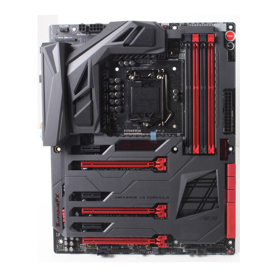
1.2.2 Motherboard layout Refer to Internal connectors and Rear I/O connection for more information about rear panel connectors and internal connectors. Chapter 1: Product introduction... -
Page 23: Layout Contents
ROG Extension connector (18-1 pin ROG_EXT) 1-45 1-28 Sonic SoundStage button (SOUNDSTAGE) TPM connector (20-1 pin TPM) 1-45 Thunderbolt header (5-pin TB_HEADER) 1-47 1-41 Front panel audio connector (10-1 pin AAFP) MPCIE COMBO III connector (42-1 pin MPCIE_COMBO_III) 1-46 ASUS MAXIMUS VII FORMULA... -
Page 24: Central Processing Unit (Cpu)
Contact your retailer immediately if the PnP cap is missing, or if you see any damage to the PnP cap/socket contacts/motherboard components. ASUS will shoulder the cost of repair only if the damage is shipment/ transit-related. -
Page 25: System Memory
The motherboard comes with four Double Data Rate 3 (DDR3) Dual Inline Memory Modules (DIMM) slots. A DDR3 module is notched differently from a DDR or DDR2 module. DO NOT install a DDR or DDR2 memory module to the DDR3 slot. Recommended memory configurations ASUS MAXIMUS VII FORMULA... -
Page 26: Memory Configurations
Memory configurations You may install 1 GB, 2 GB, 4 GB and 8 GB unbuffered and non-ECC DDR3 DIMMs into the DIMM sockets. • Memory module with memory frequency higher than 2133 MHz and its corresponding timing or the loaded XMP profile is not the JEDEC memory standard. The stability and compatibility of these memory modules depend on the CPU’s capabilities and other installed devices. - Page 27 4BZ1(XMP)" G.SKILL "G.SKILL F3-3000C12Q- 16GB (4x 4GB) 12-14-14-35 1.65 • • 16GTXDG(XMP)" G.SKILL "F3-3000C12D- 8GB (2 x 4B ) 12-14-14-35 1.65 • • 8GTXDG(XMP)" CORSAIR "CMY8GX3M2A- 8GB (2 x 4B ) 12-14-14-36 1.65 • 3000C12R(XMP)" ASUS MAXIMUS VII FORMULA 1-11...
- Page 28 DDR3 2933 MHz capability DIMM socket support Chip Chip Vendors Part No. Size Timing Voltage (Optional) Brand G.SKILL F3-2933C12D-8GTXDG(XMP) 8GB (2 x 4GB ) 12-14-14-35 1.65 • • G.SKILL F3-2933C12Q-16GTXDG(XMP) 16GB (4 x 4GB ) 12-14-14-35 1.65 • • G.SKILL F3-2933C12D-16GTXDG(XMP) 16GB (2 x 8GB ) 12-14-14-35...
- Page 29 • (Ver5.12)(XMP) G.SKILL F3-2666CL10Q-16GBZHD(XMP) 16GB ( 4x 4GB ) 10-12-12-31 1.65 • • GeIL GOC332GB2666C11QC(XMP) 32GB ( 4x 8GB ) 11-13-13-32 1.65 • • Kingston KHX26C11T2K2/8X(XMP) 8GB ( 2x 4GB ) 2666-11-13- 1.65 • 13-32 ASUS MAXIMUS VII FORMULA 1-13...
- Page 30 DDR3 2400 MHz capability DIMM socket support Chip Chip Vendors Part No. Size SS/DS Timing Voltage (Optional) Brand ADATA AX3U2400W4G11-DMV(XMP) 8GB ( 2x 4GB ) 11-13-13-35 1.65 • • ADATA AX3U2400W8G11-DMV(XMP) 16GB ( 2x 8GB ) 11-13-13-35 1.65 • • Apacer 78.BAGFL.AFD0C(XMP) 8GB ( 2x 4GB )
- Page 31 Size Chip NO. Timing Voltage (Optional) Brand AEXEA AXA3ES4GK2000LG28V(XMP) 4GB ( 2x 1.65 • • 2GB ) ASint SLA302G08-ML2HB(XMP) Hynix H5TQ2G83BFRH9C 9-9-9-27 • • GeIL GUP34GB2000C9DC(XMP) 4GB ( 2x 9-9-9-28 1.65 • • 2GB ) ASUS MAXIMUS VII FORMULA 1-15...
- Page 32 DDR3 1866 MHz capability DIMM socket support Chip Chip Vendors Part No. Size Timing Voltage (Optional) Brand CORSAIR CMD16GX3M2A1866C9 (Ver5.29) 16GB ( 2x 8GB ) 1866 9-9-9-27 • (XMP) CORSAIR CMD16GX3M4A1866C9 (Ver4.13) 16GB ( 4x 4GB ) 9-10-9-27 • • (XMP) CORSAIR CMD16GX3M4A1866C9 (Ver8.16)
- Page 33 8GB ( 2x 4GB ) 1.65 • • Silicon SP004GXLYU186NSA(XMP) 1866-9-11- • • Power 9-27 Silicon SP008GXLYU186NSA(XMP) 1866-9-11- • • Power 9-27 Team TED38GM1866C13BK Hynix H5TQ4G83AFR 13-13-13-32 • • V-color TD4G16C13-RD 1866-13-13- • • 13-32 ASUS MAXIMUS VII FORMULA 1-17...
- Page 34 DDR3 1600 MHz capability DIMM socket support Chip Vendors Part No. Size SS/DS Chip NO. Timing Voltage (Optional) Brand ADATA AD3U1600W4G11 A-DATA 3WCD-1211A 11-11- • • 11-28 ADATA AD3U1600W8G11 A-DATA 3WCD-1211A 11-11- • • 11-28 ADATA ADDU1600W4G11-B A-DATA DWND-1211A 9-9-9- •...
- Page 35 4GB ) G.SKILL F3-12800CL9Q-16GBZL(XMP) 16GB ( 4x 9-9-9- • • 4GB ) G.SKILL F3-1600C9Q-32GXM(XMP) 32GB ( 4x • • 8GB ) GeIL GUP34GB1600C7DC(XMP) 4GB ( 2x 7-7-7- • • 2GB ) (continued on the next page) ASUS MAXIMUS VII FORMULA 1-19...
- Page 36 DDR3 1600 MHz capability DIMM socket support Vendors Part No. Size Chip Brand Chip NO. Timing Voltage (Optional) KINGMAX FLGE85F-C8KL9A(XMP) KINGMAX 9-9-9- • • KINGMAX FLGF65F-C8KL9A(XMP) KINGMAX 9-9-9- • • Kingston KHX16009CD3K2/8GX(XMP) 8GB ( 2x 9-9-9- 1.65 • • 4GB ) Kingston KHX1600C9D3B1/4G(XMP) 9-9-9-...
- Page 37 28-1 Transcend TS512MLK64W6H SAMSUNG K4B4G0846B • • 11-11- 28-2 UMAX 84E44G93UM-16BPSYW UMAX U2S96D30TP-16 1600- • • 11-11- 11-28 UMAX 84E48G93UM-16BPSYW UMAX U2S96D30TP-16 1600- • • 11-11- 11-28 V-color TD4G8C11-H11 Hynix H5TQ4G83AFR 11-11- • • 11-28 ASUS MAXIMUS VII FORMULA 1-21...
- Page 38 DDR3 1333 MHz capability DIMM socket support Chip Vendors Part No. Size Chip NO. Timing Voltage (Optional) Brand AE32G1339U1-U 23EY4587MB3H • • AE34G1339U2-U 23EY4587MB3H • • Apacer 78.B1GDE.9L10C Apacer AM5D5908CEHSBG • • ASint SLA302G08-EDJ1C ASint 302G08-DJ1C • • ASint SLA304G08-EDJ1B Asint 304G08-DJ1B 9-10-...
- Page 39 ASUS exclusively provides hyper DIMM support function. • Hyper DIMM support is subject to the physical characteristics of individual CPUs. Load the X.M.P. settings in the BIOS for the hyper DIMM support. • Visit the ASUS website for the latest QVL. ASUS MAXIMUS VII FORMULA 1-23...
-
Page 40: Expansion Slots
1.2.5 Expansion slots Unplug the power cord before adding or removing expansion cards. Failure to do so may cause you physical injury and damage motherboard components. Slot No. Slot Description PCIe 2.0 x1_1 slot PCIe 3.0/2.0 x16/x8_1 slot PCIe 2.0 x1_2 slot PCIe 3.0/2.0 x8_2 slot PCIe 2.0 x1_3 slot PCIe 2.0 x4_3 slot... - Page 41 Connect a chassis fan to the motherboard connector labeled CHA_FAN1-3A/B when using multiple graphics cards for better thermal environment. • New 4th and 5th generation Intel Core™ processors support PCIe 3.0 speed rate. ® PCIe_x16/x8_1 slot switches to x8 mode when PCIe_x8_2 slots are occupied. ASUS MAXIMUS VII FORMULA 1-25...
-
Page 42: Onboard Buttons
1.2.6 Onboard buttons Onboard buttons allow you to fine-tune performance when working on a bare or open- case system. This is ideal for overclockers and gamers who continually change settings to enhance system performance. Power-on button (START) The motherboard comes with a power-on button that allows you to power up or wake up the system. - Page 43 BIOS has been restored to its default settings. • We recommend that you download and update to the latest BIOS version from the ASUS website at www.asus.com after using the MemOK! function. ASUS MAXIMUS VII FORMULA 1-27...
- Page 44 KeyBot button (KeyBot) Press this button to activate the KeyBot feature. • The KeyBot feature supports USB keyboards only. • For more information about the KeyBot feature, refer to the Software Support chapter of this user guide. Sonic SoundStage button (SOUNDSTAGE) Press this button to activate the Sonic SoundStage feature.
-
Page 45: Onboard Leds
Q LEDs check key components (CPU, DRAM, VGA card, and booting devices) in sequence during motherboard booting process. If an error is found, the corresponding LED flashes until the problem is solved. This user-friendly design provides an intuitive way to locate the root problem within seconds. ASUS MAXIMUS VII FORMULA 1-29... - Page 46 KeyBot LED (KEYBOT_LED) This LED lights up when the KeyBot button is pressed. USB BIOS Flashback LED (FLBK_LED) This LED flashes when you press the BIOS Flashback button for BIOS update. Chapter 1: Product introduction 1-30...
- Page 47 Q-Code LEDs The Q-Code LED design provides you with a 2-digit error code that displays the system status. Refer to the Q-Code table on the following page for details. ASUS MAXIMUS VII FORMULA 1-31...
-
Page 48: Q-Code Table
Q-Code table Code Description Not used Power on. Reset type detection (soft/hard). AP initialization before microcode loading System Agent initialization before microcode loading PCH initialization before microcode loading Microcode loading AP initialization after microcode loading System Agent initialization after microcode loading PCH initialization after microcode loading Cache initialization Reserved for future AMI SEC error codes... - Page 49 Recovery condition triggered by user (Forced recovery) Recovery process started Recovery firmware image is found Recovery firmware image is loaded Reserved for future AMI progress codes F5 – F7 Recovery PPI is not available (continued on the next page) ASUS MAXIMUS VII FORMULA 1-33...
- Page 50 Q-Code table Code Description Recovery capsule is not found Invalid recovery capsule FB – FF Reserved for future AMI error codes DXE Core is started NVRAM initialization Installation of the PCH Runtime Services CPU DXE initialization is started 63 – 67 PCI host bridge initialization System Agent DXE initialization is started System Agent DXE SMM initialization is started...
- Page 51 USB hot plug PCI bus hot plug Clean-up of NVRAM Configuration Reset (reset of NVRAM settings) B8– BF Reserved for future AMI codes CPU initialization error System Agent initialization error (continued on the next page) ASUS MAXIMUS VII FORMULA 1-35...
- Page 52 Q-Code table Code Description PCH initialization error Some of the Architectural Protocols are not available PCI resource allocation error. Out of Resources No Space for Legacy Option ROM No Console Output Devices are found No Console Input Devices are found Invalid password Error loading Boot Option (LoadImage returned error) Boot Option is failed (StartImage returned error)
-
Page 53: Internal Connectors
Before creating a RAID set, refer to section RAID configurations or the manual bundled in the motherboard support DVD. • When using NCQ, set the SATA Mode in the BIOS to [AHCI Mode]. Refer to section SATA Configuration for details. ASUS MAXIMUS VII FORMULA 1-37... - Page 54 ASMedia ® Serial ATA 6 Gb/s connectors (7-pin SATA6G_E1-E2; SATAEXPRESS_E1 [top]) These connectors connect to Serial ATA 6 Gb/s hard disk drives via Serial ATA 6 Gb/s signal cables. • ASMedia storage controller can only support AHCI mode. • These SATA ports are for data drives only. •...
- Page 55 USB 3.0 ports under Windows 7, Windows 8, and ® ® Windows 8.1. ® • The plugged USB 3.0 device may run on xHCI or EHCI mode depending on the operating system’s setting. ASUS MAXIMUS VII FORMULA 1-39...
- Page 56 Never connect a 1394 cable to the USB connectors. Doing so will damage the motherboard! You can connect the front panel USB cable to the ASUS Q-Connector (USB) first, and then install the Q-Connector (USB) to the USB connector onboard if your chassis supports front panel USB ports.
- Page 57 • If you want to connect a high-definition or an AC’97 front panel audio module to this connector, set the Front Panel Type item in the BIOS setup to [HD] or [AC97]. ASUS MAXIMUS VII FORMULA 1-41...
- Page 58 CPU, chassis, and optional fan connectors (4-pin CPU_FAN; 4-pin CPU_OPT; 4-pin CHA_FAN1A-3A; 4-pin CHA_FAN1B-3B) Connect the fan cables to the fan connectors on the motherboard, ensuring that the black wire of each cable matches the ground pin of the connector. •...
- Page 59 • If you are uncertain about the minimum power supply requirement for your system, refer to the Recommended Power Supply Wattage Calculator at http://support.asus. com/PowerSupplyCalculator/PSCalculator.aspx?SLanguage=en-us for details. ASUS MAXIMUS VII FORMULA 1-43...
-
Page 60: System Panel Connector
System panel connector (20-8 pin PANEL) This connector supports several chassis-mounted functions. • System power LED (2-pin PLED) This 2-pin connector is for the system power LED. Connect the chassis power LED cable to this connector. The system power LED lights up when you turn on the system power, and blinks when the system is in sleep mode. - Page 61 • The OC Panel and Front Base are purchased separately. • Visit www.asus.com for more information about the OC Panel and Front Base. TPM connector (20-1 pin TPM) This connector supports a Trusted Platform Module (TPM) system, which securely store keys, digital certificates, passwords and data. A TPM system also helps enhance the network security, protects digital identities, and ensures platform integrity.
- Page 62 T_Sensor connector (2-pin T_SENSOR1) This connector is for the thermistor cable that allows you to monitor the temperature of your motherboard’s critical components and connected devices. mPCIe Combo III connector (42-1 pin MPCIE_COMBO_III) This connector is for the bundled mPCIE Combo III card that offers expandability and connectivity solutions for an optimal system performance.
- Page 63 Thunderbolt header (5-pin TB_HEADER) This connector is for the add-on Thunderbolt I/O card that supports Intel’s Thunderbolt Technology, allowing you to connect up to six Thunderbolt-enabled devices and a DisplayPort-enabled display in a daisy-chain configuration. ASUS MAXIMUS VII FORMULA 1-47...
-
Page 64: Probeit
1.2.9 ProbeIt The ROG ProbeIt allows you to detect your system’s current voltage and OC settings. Use a multimeter to measure the ProbeIt points even during overclocking. See the illustration below to locate the respective ProbeIt points. Using ProbeIt You may connect the multitester to the motherboard as shown on the following figure. The photos above are for reference only, the actual motherboard layout and measure points location may differ by models. -
Page 65: Crosschill Copper
• route the water cooling kit from the CPU water block to the VRM zone • separate the VGA water cooling system and the CPU/VRM water cooling system for an optimal cooling result ASUS MAXIMUS VII FORMULA 1-49... - Page 66 Chapter 1: Product introduction 1-50...
-
Page 67: Chapter 2: Basic Installation
The diagrams in this section are for reference only. The motherboard layout may vary with models, but the installation steps are the same for all models. Install the ASUS Q-Shield to the chassis rear I/O panel. Place the motherboard into the chassis, ensuring that its rear I/O ports are aligned to the chassis’... - Page 68 Place nine screws into the holes indicated by circles to secure the motherboard to the chassis. DO NOT over tighten the screws! Doing so can damage the motherboard. Chapter 2: Basic Installation...
-
Page 69: Cpu Installation
2.1.2 CPU installation Ensure that you install the correct CPU designed for LGA1150 socket only. DO NOT install a CPU designed for LGA1155 and LGA1156 sockets on the LGA1150 socket. ASUS MAXIMUS VII FORMULA... -
Page 70: Cpu Heatsink And Fan Assembly Installation
2.1.3 CPU heatsink and fan assembly installation Apply the Thermal Interface Material to the CPU heatsink and CPU before you install the heatsink and fan if necessary. To install the CPU heatsink and fan assembly Chapter 2: Basic Installation... - Page 71 To uninstall the CPU heatsink and fan assembly ASUS MAXIMUS VII FORMULA...
-
Page 72: Dimm Installation
2.1.4 DIMM installation To remove a DIMM Chapter 2: Basic Installation... -
Page 73: Atx Power Connection
2.1.5 ATX Power connection ASUS MAXIMUS VII FORMULA... -
Page 74: Sata Device Connection
2.1.6 SATA device connection Chapter 2: Basic Installation... -
Page 75: Front I/O Connector
2.1.7 Front I/O Connector To install ASUS Q-Connector To install USB 2.0 connector To install front panel audio connector AAFP USB 2.0 To install USB 3.0 connector USB 3.0 ASUS MAXIMUS VII FORMULA... -
Page 76: Expansion Card Installation
2.1.8 Expansion Card installation To install PCIe x16 cards Chapter 2: Basic Installation 2-10... -
Page 77: Mpcie Combo Iii Installation
Remove the two screws at the front of the mPCIe Combo III card metal cover. Remove the screw at the back then remove the metal cover. Align and insert the M.2 (NGFF) SSD module into the M.2 slot. The M.2 (NGFF) SSD module fits in one orientation only. If it does not fit, try reversing it. ASUS MAXIMUS VII FORMULA 2-11... - Page 78 Replace the metal cover and secure the back of the metal cover with the screw that you removed in step 2. Secure the front of the metal cover with the two screws that you removed in step 1. Installing the mPCIe Combo III card To install the mPCIe Combo III card to your motherboard: Remove the screw near the 42-1 pin connector.
- Page 79 Insert the mPCIe Combo III carefully to prevent damage to the card, connector pins, or to the motherboard. Secure the mPCIe Combo III card either to the motherboard (A) or to the rear I/O shield (B) using the screw that you remove in step 1. ASUS MAXIMUS VII FORMULA 2-13...
- Page 80 Installing the Wi-Fi antenna connector To install the Wi-Fi antenna connector: Remove the bolt from the Wi-Fi antenna connector but leave the washer on the washer connector. bolt bolt washer Insert the connector into the I/O shield’s Wi-Fi port hole. Replace the bolt on the connector to secure the antenna connector and the I/O shield in place.
-
Page 81: Bios Update Utility
For more BIOS update utilities in BIOS setup, refer to the section Updating BIOS in Chapter 3. • Connect your USB keyboard on the KeyBot port if you want to use the KeyBot feature. Updating BIOS may have risks. If the BIOS program is damaged during the process and results to the system’s failure to boot up, please contact your local ASUS Service Center. ASUS MAXIMUS VII FORMULA 2-15... -
Page 82: Motherboard Rear And Audio Connections
Motherboard rear and audio connections 2.3.1 Rear I/O connection Rear panel connectors Clear CMOS button PS/2 Keyboard/Mouse combo port Optical S/PDIF OUT port HDMI port ASMedia USB 3.0 ports E1-2 ® LAN (RJ-45) port* ROG Connect button Intel USB 2.0 ports 7 and 8. Upper port is for the dedicated KeyBot port. The lower ® port supports the USB BIOS Flasback feature and the ROG Connect port. DisplayPort Intel USB 3.0 ports 3 and 4... -
Page 83: Audio I/O Connections
Mic In Mic In Center/Sub Center/Sub Orange – – woofer woofer Black – Rear Speaker Out Rear Speaker Out Rear Speaker Out Gray – – – Side Speaker Out 2.3.2 Audio I/O connections Audio I/O ports ASUS MAXIMUS VII FORMULA 2-17... - Page 84 Connect to Headphone and Mic Connect to Stereo Speakers Connect to 2.1 channel Speakers Chapter 2: Basic Installation 2-18...
- Page 85 Connect to 4.1 channel Speakers Connect to 5.1 channel Speakers ASUS MAXIMUS VII FORMULA 2-19...
- Page 86 Connect to 7.1 channel Speakers Chapter 2: Basic Installation 2-20...
-
Page 87: Starting Up For The First Time
While the system is ON, press the power button for less than four seconds to put the system on sleep mode or soft-off mode, depending on the BIOS setting. Press the power button for more than four seconds to let the system enter the soft-off mode regardless of the BIOS setting. ASUS MAXIMUS VII FORMULA 2-21... - Page 88 Chapter 2: Basic Installation 2-22...
-
Page 89: Chapter 3: Bios Setup
BIOS setup Knowing BIOS The new ASUS UEFI BIOS is a Unified Extensible Interface that complies with UEFI architecture, offering a user-friendly interface that goes beyond the traditional keyboard- only BIOS controls to enable a more flexible and convenient mouse input. You can easily navigate the new UEFI BIOS with the same smoothness as your operating system. -
Page 90: Bios Setup Program
BIOS setup program Use the BIOS Setup to update the BIOS or configure its parameters. The BIOS screen include navigation keys and brief onscreen help to guide you in using the BIOS Setup program. Entering BIOS at startup To enter BIOS Setup at startup, press <Delete> during the Power-On Self Test (POST). If you do not press <Delete>, POST continues with its routines. -
Page 91: Ez Mode
Storage Technology Click to go to Advanced mode Loads optimized default settings Click to display boot devices Selects the boot device priority The boot device options vary depending on the devices you installed to the system. ASUS MAXIMUS VII FORMULA... -
Page 92: Advanced Mode
3.2.2 Advanced Mode The Advanced Mode provides advanced options for experienced end-users to configure the BIOS settings. The figure below shows an example of the Advanced Mode. Refer to the following sections for the detailed configurations. To switch from EZ Mode to Advanced Mode, click Advanced Mode(F7) or press F7 hotkey. -
Page 93: Menu Bar
EZ Tuning Wizard(F11) This button above the menu bar allows you to view and tweak the overclocking settings of your system. It also allows you to change the motherboard’s SATA mode from AHCI to RAID mode. ASUS MAXIMUS VII FORMULA... -
Page 94: Hot Keys
Quick Note (F9) This button above the menu bar allows you to key in notes of the activities that you have done in BIOS. • The quick Note function does not support the following keyboard functions: delete, cut, copy and paste. •... -
Page 95: My Favorites
Configuration items such as Memory SPD Information, system time and date. Click Exit (ESC) or press <Esc> key to close the Setup Tree Map screen. Go to My Favorites menu to view the saved BIOS items. ASUS MAXIMUS VII FORMULA... -
Page 96: Extreme Tweaker Menu
Extreme Tweaker menu The Extreme Tweaker menu items allow you to configure overclocking-related items. Be cautious when changing the settings of the Extreme Tweaker menu items. Incorrect field values can cause the system to malfunction The configuration options for this section vary depending on the CPU and DIMM model you installed on the motherboard. - Page 97 ASUS MultiCore Enhancement [Auto] [Auto] This item allows you to maximize the oveclocking performance optimized by ASUS core ratio settings. [Disabled] This item allows you to set to default core ratio settings. CPU Core Ratio [Synch All Cores] This item allows you to set the CPU core ratio limit per core or synchronize automatically to all cores.
- Page 98 Min. CPU Cache Ratio [Auto] Allows you to set the minimum possible ratio on the Uncore part of the processor. Use the <+> or <-> keys to adjust the value. The values depend on the CPU installed. Max. CPU Cache Ratio [Auto] Allows you to set the maximum possible ratio on the Uncore part of the processor.
-
Page 99: Dram Timing Control
Configuration options: [Auto] [1] – [15] DRAM REF Cycle Time [Auto] Configuration options: [Auto] [1] – [511] DRAM Refresh Interval [Auto] Configuration options: [Auto] [1] – [65535] DRAM WRITE Recovery Time [Auto] Configuration options: [Auto] [1] – [16] ASUS MAXIMUS VII FORMULA 3-11... - Page 100 DRAM READ to PRE Time [Auto] Configuration options: [Auto] [1] – [15] DRAM FOUR ACT WIN Time [Auto] Configuration options: [Auto] [1] – [255] DRAM WRITE to READ Delay [Auto] Configuration options: [Auto] [1] – [15] DRAM CKE Minimum pulse Width [Auto] Configuration options: [Auto] [1] –...
- Page 101 Configuration options: [Auto] [1] – [14] Channel A DIMM Control [Enable Both DIMMS] Allows you to enable or disable the Channel A DIMM slots with the following configuration options: [Enable Both DIMMS] [Disable DIMM0] [Disable DIMM1] [Disable Both DIMMS] ASUS MAXIMUS VII FORMULA 3-13...
- Page 102 Configuration options: [Enable Both DIMMS] [Disable DIMM0] [Disable DIMM1] [Disable Both DIMMS] Scramble Setting [Optimized (ASUS)] Set this item to [Optimized (ASUS)] to enhance system stability. Configuration options: [Optimized (ASUS)] [Default (MRC)] MCH Full Check [Auto] Enable this item to enhance the stability of your system. Disable this item to enhance the DRAM overclocking capability.
- Page 103 300 KHz to 500 KHz with an interval of 50 KHz. Do not remove the thermal module when the manual mode is selected. The thermal conditions should be monitored. The following item appears only when the CPU VRM Switching Frequency is set to [Auto]. ASUS MAXIMUS VII FORMULA 3-15...
- Page 104 VRM Spread Spectrum [Disabled] This item allows to enhance the system stability. Configuration options: [Disabled] [Enabled] CPU Power Phase Control [Auto] This item allows you to set the power phase control of the CPU. Configuration options: [Auto] [Standard] [Optimized] [Extreme] DO NOT remove the thermal module when setting this item to [Power Phase Response].
- Page 105 Configuration options: [Enabled] [Disabled] Turbo Mode [Enabled] Allows you to enable your processor cores to run faster than the base operating frequency when it is below power, current and specification limit. Configuration options: [Disabled] [Enabled] ASUS MAXIMUS VII FORMULA 3-17...
- Page 106 The following items appear only when you set the Turbo Mode to [Enabled]. Turbo Mode Parameters CPU Integrated VR Current Limit [Enabled] This tiem allows the system to dynamically adjusts the CPU voltage and core frequency when enabled. Configuration options: [Disabled] [Enabled] CPU Internal Power Switching Frequency Frequency Tuning Mode [Auto] Allows you to increase or decrease the switching frequency of the internal...
- Page 107 Use <+> or <-> key to adjust the value. The values range from 0A to 30A at 1Amp increment. Fully Manual Mode [Disabled] Enable this item to open up support of voltage control via ROG Connect and OC Panel. Configuration options: [Disabled] [Enabled] ASUS MAXIMUS VII FORMULA 3-19...
- Page 108 CPU Core Voltage [Auto] Configures the amount of Voltage fed to the cores of the processor. Increase when increasing Core Frequency. Use <+> or <-> key to adjust the value. The values range from 1.050000V to 2.200000V at 0.003125V increment. Configuration options: [Auto] [Manual Mode] [Offset Mode] Appear only when you set the CPU Core Voltage to [Manual Mode].
- Page 109 PCIE controller and the PCU (power control unit). Increase the voltage to enhance the overclocking capability. You can use the <+> or <-> keys to adjust the value. The values range from 0.001 V to 0.999 V with a 0.001 V interval. ASUS MAXIMUS VII FORMULA 3-21...
- Page 110 CPU Analog I/O Voltage Offset Mode Sign [+] To offset the voltage by a positive value. [–] To offset the voltage by a negative value. CPU Analog I/O Voltage Offset [Auto] This item allows you to set the amount of voltage fed to the analog portion of the I/O on the CPU.
- Page 111 (electromagnetic disturbance) generated by the BCLK. Set this item to [Enabled] for EMI reduction, or set this item to [Disabled] to enhance BCLK overclocking. Configuration options: [Auto] [Disabled] [Enabled] BCLK Recovery [Enabled] This item allows you to enable the BCLK Recovery feature. Configuration options: [Disabled] [Enabled] [Ignore] ASUS MAXIMUS VII FORMULA 3-23...
-
Page 112: Main Menu
Main menu The Main menu screen appears when you enter the Advanced Mode of the BIOS Setup program. The Main menu provides you an overview of the basic system information, and allows you to set the system date, time, language, and security settings. Chapter 3: BIOS setup 3-24... - Page 113 RTC RAM via the Clear CMOS button. • The Administrator or User Password items on top of the screen show the default [Not Installed]. After you set a password, these items show [Installed]. ASUS MAXIMUS VII FORMULA 3-25...
-
Page 114: Administrator Password
Administrator Password If you have set an administrator password, we recommend that you enter the administrator password for accessing the system. Otherwise, you might be able to see or change only selected fields in the BIOS setup program. To set an administrator password: Select the Administrator Password item and press <Enter>. -
Page 115: Advanced Menu
The Advanced menu items allow you to change the settings for the CPU and other system devices. Be cautious when changing the settings of the Advanced menu items. Incorrect field values can cause the system to malfunction. ASUS MAXIMUS VII FORMULA 3-27... -
Page 116: Cpu Configuration
3.6.1 CPU Configuration The items in this menu show the CPU-related information that the BIOS automatically detects. The items in this menu may vary based on the CPU installed. Intel Adaptive Thermal Monitor [Enabled] This item allows you to protect the CPU by decreasing its frequency as it reaches the thermal throttle point. - Page 117 This item allows your system to adjust the CPU’s voltage and cores frequency, resulting in decreased power consumption and heat production. [Disabled] The CPU runs at its default speed. [Enabled] The system controls the CPU speed. ASUS MAXIMUS VII FORMULA 3-29...
- Page 118 CPU C-States [Auto] This item allows you to set the power saving of the CPU states. Configuration options: [Auto] [Disabled] [Enabled] The following items appear only when you set the CPU states to [Enabled]. Enhanced C1 State [Enabled] This item allows your CPU to reduce power consumption when the system is in idle mode.
-
Page 119: Pch Configuration
[Enabled]. This item supports Intel Rapid Storage Technology when the partition size is greater than the Active Page Threshold size. When set to zero (0), it will go to Auto mode and checks if the partition size is enough at S3 entry. ASUS MAXIMUS VII FORMULA 3-31... -
Page 120: Pch Storage Configuration
Hybrid Hard Disk Support [Disabled] This item allows you to enable or disable the hybrid hard disk support for a faster resume time. Configuration options: [Enabled] [Disabled] Intel Smart Connect Technology Support [Disabled] This item allows the system to support Intel Smart Connect Technology that periodically refreshes selected applications when the system is in sleep mode. - Page 121 S.M.A.R.T. (Self-Monitoring, Analysis and Reporting Technology) is a monitoring system that shows a warning message during POST (Power-on Self Test) when an error occurs in the hard disks. Press <Enter> to set this item On or Off. Configuration options: [On] [Off] ASUS MAXIMUS VII FORMULA 3-33...
- Page 122 SATA6G_1 (Red) - SATA6G_6 (Red) Press <Enter> to rename the Intel SATA ports. SATA6G_1 (Red) - SATA6G_6 (Red) [Enabled] This item allows you to enable or disable the selected SATA port. Configuration options: [Disabled] [Enabled] Hot Plug [Disabled] These items appears only when the SATA Mode Selection is set to [AHCI] and allows you to enable or disable SATA Hot Plug Support.
-
Page 123: System Agent Configuration
Configuration options: [Disabled] [Enabled] DMI Configuration Enable this item for the DMI (Direct media interface) to run at PCI-E 2.0 speed. DMI Gen 2 [Enabled] Configuration options: [Enabled] [Disabled] ASUS MAXIMUS VII FORMULA 3-35... -
Page 124: Memory Configuration
NB PCI-E Configuration Allows you to configure the NB PCI Express settings. PCIEx16_1/2 Link Speed [Auto] Allows you to select the operating speed of the PCI-EX16_1 /2 speed. Configuration options: [Auto] The system will automatically select the PCI-E x16 port speed. [Gen1] The PCI-EX16 port will run at PCI-E 1.0 speed. -
Page 125: Usb Configuration
Support EHCI by BIOS for operating systems without EHCI support. USB Single Port Control Allows you to enable or disable the individual USB ports. Refer to the Motherboard layout section for the location of the USB ports. ASUS MAXIMUS VII FORMULA 3-37... -
Page 126: Platform Misc Configuration
3.6.6 Platform Misc Configuration The items in this menu allow you to configure the platform-related features. PCI-E Native Power Management [Disabled] Enable this item to enhance the PCI-E power saving condition. Configuration options: [Disabled] [Enabled] The following item appears only when you set the PCI Express Native Power Management to [Enabled]. -
Page 127: Onboard Devices Configuration
Sets the front panel audio connector (AAFP) mode to high definition audio. [AC97] Sets the front panel audio connector (AAFP) mode to legacy AC’97 SPDIF Out Type [SPDIF] [SPDIF] Sets to an SPDIF audio output. [HDMI] Sets to an HDMI audio output. ASUS MAXIMUS VII FORMULA 3-39... - Page 128 Bluetooth Controller [Enabled] This item allows you to enable or disable the Bluetooth Controller. Configuration options: [Disabled] [Enabled] Wi-Fi Controller [Enabled] This item allows you to enable or disable the Wi-Fi Controller. Configuration options: [Disabled] [Enabled] PCI-EX4_3 Slot(black) Bandwidth [Auto] [Auto] If PCIeX4_3 slot is not occupied by X4 device, both the PCIeX4_3 slot and the SATAEXPRESS_E1 run at X2 mode.
- Page 129 Intel LAN PXE Option ROM [Disabled] This item appears only when Intel LAN Controller is set to [Enabled].This item allows you to enable or disable the Intel LAN preboot execution environment (PXE) option ROM. Configuration options: [Disabled] [Enabled] ASUS MAXIMUS VII FORMULA 3-41...
-
Page 130: Apm Configuration
3.6.8 APM Configuration ErP Ready [Disabled] Allows you to switch off some power at S4+S5 or S5 to get the system ready for ErP requirement. When set to [Enabled], all other PME options will be switched off. Configuration options: [Disabled] [Enabled(S4+S5] [Enabled(S5)] Restore AC Power Loss [Power Off] [Power Off] The system goes into OFF state after an AC power loss. -
Page 131: Network Stack Configuration
Onboard LED [Enabled] This item allows you to enable all the onboard LEDs. Configuration options: [Enabled] [Disabled] ROG logo LED [Enabled] This item allows you to enable or disable the ROG logo. Configuration options: [Enabled] [Disabled] ASUS MAXIMUS VII FORMULA 3-43... -
Page 132: Monitor Menu
Monitor menu The Monitor menu displays the system temperature/power status, and allows you to change the fan settings. Qfan Tuning Click this item to automatically detect the lowest speed and configure the minimum duty cycle for each fan. Anti Surge Support [Enabled] Enable this item for Over Voltage Protection (OVP) and Under Voltage Protection (UVP) functions. -
Page 133: Fan Speed Control
Use the <+> or <-> keys to adjust the minimum CPU fan duty cycle. The values range from 0% to 100%. When the CPU temperature is under 40ºC, the CPU fan will operate at the minimum duty cycle. ASUS MAXIMUS VII FORMULA 3-45... - Page 134 Chassis Fan 1/2/3 Q-Fan Control [DC Mode] [Disabled] Disables the Chassis Q-Fan control feature. [DC mode] Enable the chassis Q-Fan control in DC mode for 3-pin chassis fan. [PWM mode] Enable the chassis Q-Fan control in PWM mode for 4-pin chassis fan. Chassis Fan 1/2/3 Q-Fan Source [CPU] The assignment fan will be controlled according to the selected temperature source.
-
Page 135: Boot Menu
The values range from 60% to 100%. When the chassis temperature is under 40ºC, the chassis fan will operate at the minimum duty cycle. Boot menu The Boot menu items allow you to change the system boot options. Scroll down to display the other BIOS items. ASUS MAXIMUS VII FORMULA 3-47... - Page 136 Fast Boot [Enabled] [Disabled] Allows your system to go back to its normal boot speed. [Enabled] Allows your system to accelerate the boot speed. The following items appear only when you set the Fast Boot to [Enabled]. SATA Support [All Devices] [All Devices] All devices connected to SATA ports are available during POST.
- Page 137 The Option ROM Messages will be shown during the POST. [Disabled] Only the ASUS logo will be shown during the POST. Interrupt 19 Capture [Disabled] Enable this item to allow the option ROMs to trap the interrupt 19. Configuration options:...
-
Page 138: Secure Boot
CSM (Compatibility Support Module) This item allows you to configure the CSM (Compatibility Support Module) items to fully support the various VGA, bootable devices and add-on devices for better compatibility. Launch CSM [Enabled] [Auto] The system automatically detects the bootable devices and the add- on devices. - Page 139 Load Default db Allows you to load the downloaded db from a USB storage device. Append Default db Allows you to load the additional db from a storage device so that more images can be loaded securely. ASUS MAXIMUS VII FORMULA 3-51...
-
Page 140: Boot Option Priorities
OS in Safe Mode, press <F8 > after POST (Windows 8 not supported). • To select the boot device during system startup, press <F8> when ASUS Logo appears. Boot Override These items displays the available devices. The number of device items that appears on the screen depends on the number of devices installed in the system. -
Page 141: Tool Menu
To launch ROG SSD Secure Erase, click Tool > ROG SSD Secure Erase on the Advanced mode menu. Check the ASUS support site for a full list of SSDs tested with Secure Erase. The drive may become unstable if you run Secure Erase on an incompatible SSD. -
Page 142: Graphics Card Information
Locked. SSDs might be locked if the Secure Erase process is either incomplete or was stopped. This may be due to a third party software that uses a different password defined by ASUS. You have to unlock the SSD in the software before proceeding with Secure Erase. -
Page 143: Asus Overclocking Profile
Key in the profile name to save current BIOS settings to profile 1 to 8. Save to Profile Saves the current BIOS settings to profile number 1 to 8. load/Save Profile from/to USB Drive Allows you to save or load selected progiles to or from a USB drive. ASUS MAXIMUS VII FORMULA 3-55... -
Page 144: Asus Spd Information
3.9.5 ASUS SPD Information Allows you to view the DRAM SPD information. DIMM slot number [DIMM_B2] Allows you to select the DIMM slot number to show the plugged DRAM Serial Presence Detect (SPD) information. Configuration options: [DIMM_A1] [DIMM_A2] [DIMM_B1] [DIMM_ Some DRAM manufacturers may not be recognized. -
Page 145: Rog Oc Panel H-Key Configure
This item allows you to save the new values of the CPU Core Voltage, CPU Input Voltage, BCLK Frequency, and CPU Ratio. Load from profile This item allows you to load the previous values of the CPU Core Voltage, CPU Input Voltage, BCLK Frequency, and CPU Ratio. ASUS MAXIMUS VII FORMULA 3-57... -
Page 146: Exit Menu
3.10 Exit menu The Exit menu items allow you to load the optimal default values for the BIOS items, and save or discard your changes to the BIOS items. You can access the EZ Mode from the Exit menu. Load Optimized Defaults This option allows you to load the default values for each of the parameters on the Setup menus. -
Page 147: Updating Bios
® ASUS EZ Flash 2: Updates the BIOS using a USB flash drive. ASUS CrashFree BIOS 3: Restores the BIOS using the motherboard support DVD or a USB flash drive when the BIOS file fails or gets corrupted. ASUS BIOS Updater: Updates the BIOS in DOS environment using the motherboard support DVD and a USB flash disk drive. -
Page 148: Asus Ez Flash
3.11.2 ASUS EZ Flash 2 ASUS EZ Flash 2 allows you to update the BIOS without having to use a bootable floppy disk or an OS-based utility. Before you start using this utility, download the latest BIOS from the ASUS website at www.asus.com. -
Page 149: Asus Crashfree Bios
The BIOS file in the motherboard support DVD may be older than the BIOS file published on the ASUS official website. If you want to use the newer BIOS file, download the file at http://support.asus.com and save it to a USB flash drive. -
Page 150: Asus Bios Updater
3.11.4 ASUS BIOS Updater ASUS BIOS Updater allows you to update the BIOS in DOS environment. The screen captures used in this section are for reference only and may not be exactly the same as actually shown on your computer screen. - Page 151 [Enter] Select or Load [Tab] Switch [V] Drive Info [Up/Down/Home/End] Move [Esc] Exit Press <Tab> to switch from Drives panel to Files panel then press <Up/Down or Home/ End> keys to select the BIOS file and press <Enter>. ASUS MAXIMUS VII FORMULA 3-63...
- Page 152 After the BIOS Updater checks the selected BIOS file, select Yes to confirm the BIOS update. Are you sure you want to update the BIOS? The BIOS Backup feature is not supported due to security regulations. Select Yes then press <Enter>. When BIOS update is done, press <ESC> to exit BIOS Updater.
-
Page 153: Chapter 4: Software Support
• Motherboard settings and hardware options vary. Use the setup procedures presented in this chapter for reference only. Refer to your OS documentation for detailed information. Support DVD information The contents of the support DVD are subject to change at any time without notice. Visit www.asus.com for updates. 4.2.1 Running the support DVD Ensure that you have an Administrator account before running the support DVD in Windows 7, Windows 8, or Windows 8.1 OS. ® ® ® To run the support DVD Place the Support DVD into the optical drive. 2. In the AutoPlay dialog box, click Run ASSETUP.exe. If the AutoPlay dialog box does not appear, browse the contents of the support DVD and ASUS motherboard support double-click or tap \\bin\ASSETUP.EXE to launch the DVD main menu ASUS MAXIMUS VII FORMULA... -
Page 154: Obtaining The Software Manuals
Contains ROG related videos. Shows the available device drivers if the system detects installed devices. Click to display the ASUS contact information. Install the necessary drivers to use Click to display product the devices. -
Page 155: Software Information
Most of the applications in the support DVD have wizards that will conveniently guide you through the installation. View the online help or readme file that came with the software application for more information. AI Suite 3 AI Suite 3 is an all-in-one interface that integrates several ASUS utilities and allows you to launch and operate these utilities simultaneously. Installing AI Suite 3 Ensure that you have an Administrator account before installing AI Suite 3 in Windows 7, ® Windows 8, or Windows 8.1 OS. ® ® To install AI Suite 3 on your computer: Windows 7 OS ® Place the Support DVD into the optical drive. 2. In the AutoPlay dialog box, click Run ASSETUP.exe then select the Utilities tab 3. From the Utilities tab, click AI Suite 3 then follow the succeeding onscreen instructions. ASUS MAXIMUS VII FORMULA... - Page 156 If the ASUS motherboard support DVD main menu did not appear, try the following steps: Go to the Start Screen then click or tap the Desktop app. On the lower left corner of the Desktop, click or tap File Explorer then select your DVD drive and tap or double-click the Setup application. Launching AI Suite 3 Windows 7 OS ® From the Desktop, click Start > All Programs > ASUS > AI Suite 3 > AI Suite 3. You can also launch AI Suite 3 in Windows 7 by clicking on the Notification area. ® Windows 8 / Windows 8.1 OS ® ®...
- Page 157 Click to launch AI Suite 3 menu bar AI Suite 3 main menu bar Dual Intelligent USB BIOS Processor 5 Ai Charger+ EZ Update Flashback Wi-Fi Engine System USB Charger+ Push Notice Version USB 3.0 Boost Information • Some functions in the AI Suite 3 main menu in this user guide may vary depending on the motherboard model. • Refer to the software manual in the support DVD or visit the ASUS website at www.asus.com for detailed software configuration. ASUS MAXIMUS VII FORMULA...
-
Page 158: Dual Intelligent Processors 5
Dual Intelligent Processors 5 ASUS Dual Intelligent Processors 5 combines TPU, EPU, DIGI+ Power Control, Fan Xpert 3, and Turbo App functions to push the system’s performance to its optimal potential. It automatically balances the system’s performance, power saving, levels, and fan settings via the user-friendly AI Suite 3 utility. 5-Way Optimization The 5-Way Optimization function dynamically optimizes your PC based on real-time usage to provide the best system status. It covers the essential areas such as CPU performance, energy saving, stable digital power, cool and quiet fan control, and includes tailored settings for your apps to ensure your PC is ready for gaming, entertainment, productivity, or just about anything. Click or tap this 5-Way Optimization button to auto-detect and tune the best settings for your system DO NOT remove your fan during the tuning process. Chapter 4: Software support... -
Page 159: Turbo Processing Unit (Tpu)
Click or tap to apply the the saved profile default values adjustments Click or tap to save the adjustment into a profile Click or tap to undo the adjustments • Set the CPU Ratio Setting item in BIOS to [Auto] before using the CPU Frequency in TPU. Refer to the BIOS Setup chapter of your motherboard’s user guide for details. • The CPU Frequency bars show the status of the CPU cores, which vary with your CPU model. ASUS MAXIMUS VII FORMULA... - Page 160 Graphics card Tick to select a mode for graphics card configuration Click to apply the adjustments Click to Click to perform undo the Click to load profile Fan Tuning adjustments Click to save the adjustment into a profile Move the sliders or Click or tap adjust the settings Chapter 4: Software support...
-
Page 161: Energy Processing Unit (Epu)
Tick to select a setting for Click to undo the Click to apply the Click to enable the Voltage Decrement adjustments adjustments default settings • When you enable Configured Max CPU Power for advanced energy saving condition, the CPU frequency may display 800 MHz in the Windows OS information ® of your computer. However, the true CPU frequency varies depending on the wattage that you manually set. You can adjust the CPU wattage from the lowest base on your preferred default value. • Configured Max CPU Power may decrease the total power delivery to the CPU and affects the CPU performance under system heavy load. To restore your system to its default settings, reboot your computer. ASUS MAXIMUS VII FORMULA... -
Page 162: Digi+ Power Control
DIGI+ Power Control ASUS DIGI+ Power Control features the revolutionary and innovative digital VRM and DRAM Voltage controllers. These controllers offers ultra-precise memory and voltage tuning for optimal system efficiency, stability and performance. The following screens are for reference only. Configuration options varies depending on the motherboard model. Click or tap to switch Click or tap to undo Click or tap to between screens the changes apply the changes CPU Power Phase Control Increase the phase number under a heavy system load to get more transient and better thermal performance. Reduce the phase number under a light system load to increase the VRM efficiency. CPU VRM Switching Frequency Enables spread spectrum to enhance system stability. -
Page 163: Fan Xpert 3
Click to set the balanced Click to increase the fan’s Click to switch between CPU speed for a high cooling configuration between the and chassis fan screens capability fan’s noise level and speed ASUS MAXIMUS VII FORMULA 4-11... -
Page 164: Turbo App
Turbo App Turbo App allows you customize the system performance, network priority, and audio setting of an application. When an application is on the Turbo App List, you can allocate the CPU frequency, assign a network priority, and define the audio setting of the selected application. Click to refresh the list of running applications Click to assign a specific application(.exe) into Turbo App list Click to scroll up/down Click to apply the changes Click to undo the changes Applications list pane Displays all the running applications on your system. -
Page 165: Usb 3.0 Boost
Click to enable UASP or Turbo Mode to the USB Click to select a USB device device for a faster data transfer rate Ensure to connect your USB 3.0 device to the USB 3.0 ports that support USB 3.0 Boost. Refer to the Rear I/O connection section of your user guide for more details. • USB 3.0 Boost automatically detects the USB 3.0 devices that support UASP. For a list of UASP-supported USB 3.0 devices, visit the ASUS website at www.asus.com. • The data transfer speed varies with USB devices. For a higher data transfer performance, use a USB 3.0 device. ASUS MAXIMUS VII FORMULA 4-13... -
Page 166: Ez Update
EZ Update EZ Update is a utility that allows you to automatically update your motherboard’s software, drivers, or BIOS. With this utility, you can also manually update the BIOS and select the boot logo that will display during POST. Launching EZ Update To launch EZ Update, click or tap on the top-right corner of the AI Suite 3 main menu, then click EZ Update on the AI Suite 3 main menu bar. EZ Update screen Click to automatically update your motherboard’s driver, software and firmware Click to select a Click to update Click to search and boot logo the BIOS select the BIOS file Chapter 4: Software support... -
Page 167: System Information
System Information This utility displays the detailed information and settings of the installed motherboard, CPU, and memory. Launching the System Information To launch System Information, click or tap on the top-right corner of the AI Suite 3 main menu, then select System Information. Viewing the motherboard information Click or tap the MB tab to view the motherboard’s information. Viewing the CPU information Click or tap the CPU tab to view the processor’s information. ASUS MAXIMUS VII FORMULA 4-15... - Page 168 Viewing the SPD information Click or tap the SPD tab to view the memory’s information. Chapter 4: Software support 4-16...
-
Page 169: Usb Bios Flashback
BIOS Click or tap update available to cancel the for download download schedule setting Click or tap to apply the download schedule setting Scheduling the BIOS download In the Download Setting field, tick Schedule (days) then select the number of days for the BIOS download schedule. Click or tap Apply to save the BIOS download schedule. Click or tap Cancel to cancel the download schedule. ASUS MAXIMUS VII FORMULA 4-17... -
Page 170: Usb Charger
Click or tap to discard the settings Click or tap to select the type of USB device that you wish to charge when the system is off Ensure to connect your USB device into the USB port that supports this utility. Refer to the Rear I/O connection section of this user guide for more details. • USB Charger+ does not support USB hubs, USB extension cables, and generic USB cables. • USB Charger+ may not recognize some ASUS devices due to varying design. Chapter 4: Software support 4-18... -
Page 171: Push Notice
Click or tap to Click or tap to apply the settings discard the settings You can also enable the Push Notice via the Push Notice shortcut on the lower-right corner of your screen. To do this, click or tap << then click or tap then select Pairing your computer and smart device To pair your computer and smart device: On your smart device, tap to launch Push Notice. Push Notice Tap Push Scan then tap the name of your computer that you want to pair with. To pair your computer and smart device, ensure that both are connected to the same wireless network. ASUS MAXIMUS VII FORMULA 4-19... - Page 172 Setting up PC Mode alerts of your computer This feature allows you to restart, shut down, or put your computer to sleep mode and sends an alert to your smart device. Tick these to enable mode alerts Tick to select the smart device Set the day and time to enable the PC modes Set the minutes to send the alert before the PC mode/s activation Key in your messages for more information...
-
Page 173: Sending Messages To Your Smart Device
Viewing your computer status on your smart device Tap on your smart device to launch Push Notice. Push Notice Tap to delete PC Tap to view PC alerts mode alerts Tap to view PC status alerts Tap to view PC sent messages Tap to scan more host computers ASUS MAXIMUS VII FORMULA 4-21... -
Page 174: Wi-Fi Engine
Wi-Fi Engine To use Wi-Fi Engine, click or tap the on the top edge of the AI Suite 3 main menu, then select Wi-Fi Engine. Click to connect to a wireless access point Click to set up your computer as a wireless access point Using the Client Mode The Client mode allows you to connect your system to a wireless access point or a host router. To use the client mode: On the Wi-Fi Engine menu, click Client Mode to launch Network Connections. From the Network Connections window, double-click to select a network adapter. From the list of available networks, click to select a network that you want to connect to. Some networks may require you to key in a password. - Page 175 Key in your password for confirmation Click to disable AP mode Click to enable AP mode Click to go back to Click to select a previous screen network connection • In this mode, the Internet Connection Sharing may depend on the Bluetooth/Internet device’s driver support. • Due to Windows 8 limitation, it may take one to two minutes to set up the AP mode ® for the first time. ASUS MAXIMUS VII FORMULA 4-23...
-
Page 176: Wi-Fi Go! And Remote Go
Extra high density type (120 ldpi) (160 mdpi) (240 hdpi) (320 xhdpi) WXGA 1536 x 1152 2048 x 1536 (1280 x 800) Screen 1024 x 600 1024 x 768 1920 x 1152 2560 x 1536 Resolution 1280 x 768 1920 x 1200 2560 x 1600 ASUS Account Login Wi-Fi GO! gives you complete control of your PC anytime and anywhere. Create and login the same ASUS Account on your PC and smart devices for public-to-private network functions. • Remote Desktop and File Transfer support public-to-private networks feature. • You can access the ASUS Account tab by clicking from Wi-Fi GO! main page. Chapter 4: Software support 4-24... - Page 177 Creating an ASUS account Ensure that you have an internet connection before you create an account. To create a new ASUS Account: 1. Click or tap Create a New Account on your PC or smart device. The browser will direct you to the ASUS website (www.asus.com). 2. From the ASUS website, click or tap Sign Up then follow onscreen instructions to complete the registration. Logging in To log-in using your PC: Launch Wi-Fi GO! on your PC. A login notice is displayed when you launch Wi-Fi GO! for the first time on your PC. To stop this notice from appearing again, tick Don’t remind me again then click Go to Login. From the log-in window, key in your ASUS account and password (A) then click Login (B). ASUS MAXIMUS VII FORMULA 4-25...
- Page 178 Wi-Fi GO! & NFC Remote V2.00.00 or later versions. Using Wi-Fi GO! To launch Wi-Fi GO!, click the ASUS HomeCloud shortcut on your desktop, then select Wi- Fi GO! from the mini bar. Click to set a password or log in using your ASUS Account Use your smart device to scan QR Wi-Fi GO! menu Codes for more information...
- Page 179 Using Wi-Fi GO! & NFC Remote To use the Wi-Fi GO! & NFC Remote: Connect your smart device to the same Wi-Fi network as your computer or log in on your computer and smart devices using the same ASUS account to fully utilize the Wi- Fi GO! functions across different networks. On your smart device, tap then tap Enter. Wi-Fi GO! & NFC Remote From the list of scanned PCs, tap the computer that you want to connect with your smart device. Wi-Fi GO! & NFC Remote interface main page Cloud GO! Remote Desktop File Transfer Remote Keyboard & Mouse The screenshots are for reference only and vary with the type of smart device. ASUS MAXIMUS VII FORMULA 4-27...
- Page 180 Using the Wake-on-LAN If you want to wake up your computer using the smart device, ensure that you enable the computer’s Wake-on-LAN settings. To configure your computer’s Wake-on-LAN settings: From BIOS Setup, go to Advanced > APM Configuration then set Power On By PCI-E/PCI to [Enabled]. From Windows OS, do the following: ® On your desktop, click Start, right-click Computer > Manage to launch the Computer Management screen. Click Device Manager to view all the installed devices. Click Network Adapters, right-click the installed module card (Broadcom or Atheros) then click Properties > Power Management tab. Tick these items Allow this device to wake up the computer and Only allow a magic packet to wake the computer. For 802.11ac standard Wi-Fi GO! Card, the Wake-on-LAN function will be supported in the later version for Windows 8 operating system.
- Page 181 Click or tap to go back Click or tap to synchronize cloud contents or to to the previous screen create a back up to your local drive Click or tap to go back to Wi-Fi GO!/Remote GO! screen ASUS MAXIMUS VII FORMULA 4-29...
- Page 182 Remote Desktop Remote Desktop allows you to remotely control your desktop in real-time using your smart device. The System User Account Control (UAC) will be set to Never Notify when using Remote Desktop function. The UAC level will return to your previous settings after you exit Remote Desktop. To use Remote Desktop: On your smart device, tap Remote Desktop. Remote Desktop interface for Windows ® Tap to view the cursor Tap to launch the Charms bar Tap to launch the smart device’s keypad. Long press to switch between multitouch and mouse mode.
- Page 183 Remote Desktop Control Notification This function allows you to send the control authorization to a smart device and directly start using Remote Desktop in your device. To use Remote Desktop Control Notification: 1. Click Select Device. 2. Select a device from the drop list. 3. Click Send to send the Remote Desktop control authorization to the selected device. This function requires the Push Notice feature to be installed. You can get the PUSH Notice installer from the bundled support DVD or download the latest installer from www.asus.com. ASUS MAXIMUS VII FORMULA 4-31...
-
Page 184: File Transfer
Click or tap File Transfer . Click or tap Setting to select the destination for your transferred files. Right-click the file then select Send to > [Device Name]. After the file transfer is complete, click or tap OK. • To receive files on your iOS device, go to Settings > Privacy > Photos then turn on the Wi-Fi GO! & NFC Remote. • Find your transferred files from <SD Card>\Wi-Fi GO! for Android devices and Camera roll for iOS devices. Transferring files from smart device to computer To transfer files from smart device to computer: Tap File Transfer > Enter. Tick the files that you want to send to your computer, then tap Send. Find your transferred files from X:\Users\Documents\ASUS HomeCloud\Wi-Fi GO!\File Transfer\ or click Setting to select a new storage location. Chapter 4: Software support 4-32... - Page 185 Tap to switch between and magnifier function Start menu running tasks and apps Input field Mouse tap area Tap to mimic right- Control keys Tap to mimic left- click mouse function click function Slide up/down to scroll ASUS MAXIMUS VII FORMULA 4-33...
-
Page 186: Ai Charger
Ai Charger+ Ai Charger+ allows you to fast-charge your portable BC 1.1* mobile devices on your computer’s USB port three times faster than the standard USB devices**. Launching Ai Charger+ To launch Ai Charger+, click or tap on the top-right corner of the AI Suite 3 main menu, then select Ai Charger+. Ai Charger+ is available only in selected motherboard models. Ai Charger+ screen Tick to enable or Click or tap to apply disable Ai Charger+ the selection • * Check the manufacturer if your USB device is a Battery Charging Specification 1.1 (BC 1.1) compliant or compatible device. • ** Actual charging speeds may vary depending on the charging rate and specifications of your USB device. • To ensure normal charging function, disconnect and reconnect your USB device every time you enable or disable Ai Charger+. • Ai Charger+ does not support USB hubs, USB extension cables, and generic USB cables. -
Page 187: Rog Audio Features
ROG Audio features Installing the Software Follow the installation wizard to install the Realtek Audio Manager driver from the support ® DVD that is bundled with the motherboard. If the Realtek audio software is correctly installed, you will find the Realtek HD Audio ® ® Manager icon on the taskbar. Double-click or tap on the icon to display the Realtek HD ® Audio Manager. Realtek ® HD Audio Manager Sonic Studio Sonic Studio is an audio suite that offers six audio controls: Reverb, Bass Boost, Equalizer, Voice Clarity, Smart EQ (Smart Volume), and Virtual Surround. Virtual Surround is dedicated for 2-channel headset and offers one of the best virtual surround technology for gaming. ASUS MAXIMUS VII FORMULA 4-35... - Page 188 Equalizer switch Click to enable. This item allows you to adjust the parametric EQ settings according to your preference. Equalizer advanced settings This item available only when the Equalizer switch is enabled. This item allows you to configure the Equalizer settings. You can manually set or customized your setting or choose from any of the preset equalizer settings available. Equalizer presets Displays the current or selected equalizer preset. Bass Boost switch Click to boosts the bass effects. Use the slider to adjust the sound of the bass effect. Voice Clarity switch Click to enable this item. Voice clarity extracts human voice for better dialog/audio communication or to hear vocals more clearly when listening to a music. Smart EQ (Smart Volume) switch Dynamically adjust the EQ so you can hear more details. Virtual Surround switch This item lets you experience 7.1 CH virtual surround from your headset when enabled. Reverb switch The Reverb effect is part of the Virtual Sound Stage effects that lets you choose other reverb presets. Reverb presets Click to choice and select a reverb effect from the different environmental spaces for reverb effects.
-
Page 189: Sonic Senseamp
Sonic SenseAmp Sonic SenseAmp is an exclusive ROG invention that is a built-in headphone AMP on onboard audio with three AMP levels adjustment. It detects your headphone’s impedance and adjusts the built-in AMP accordingly. Sonic SenseAmp only works on front panel. When you plug a headphone into the front headphone jack, Sonic SenseAmp displays a pop- up window that displays “Detecting headphone impedance”. After detecting the headphone’s impedance, Sonic SenseAmp displays another pop-up window similar to the one shown below. Refer to the table below on the behavior of Sonic SenseAmp when adjusting the impedance of the detected headphone: Amplify Level is automatically set at Performance 65 ohm or below Amplify Level is automatically set at Powerful 65 ohm to 150 ohm Amplify Level is automatically set at Extreme > 150 ohm The device plugged in detected as other device Other device ASUS MAXIMUS VII FORMULA 4-37... - Page 190 After you close the pop-window, Sonic SenseAmp enters speaker configuration and displays the adjusted headphone impedance. Click to manually adjust the amplify level Displays the impedance of your headphone Chapter 4: Software support 4-38...
-
Page 191: Sonic Soundstage
This feature is only available for front panel Headphone output. • You can enable this feature by enabling the dedicated SoundStage button on your motherboard. Refer to the Onboard buttons section on this user guide for more information. Click any of the four preset gaming profiles Use the slider to manually adjust the setting of an item Crossing Move the slider to adjust the amount of cross channel mixing. Revert Move the slider to revert the main audio source. Space Move the slider to adjust and virtualize the space sound. Crossing gain This item only works when Crossing and Revert is enabled. Move the slider to adjust the hardness of the wall. ASUS MAXIMUS VII FORMULA 4-39... -
Page 192: Dts Connect
DTS Connect DTS Connect delivers excellent audio entertainment across all formats and works with 4, 5.1 and 7.1 channels of incredible surround sound . It also allows you to connect your PC to a home theatre system. Control settings panel Chapter 4: Software support 4-40... -
Page 193: Sonic Radar Ii
Each option has its own settings and menus. Click to reset to the default settings Click to start the test tone Use the sliders to adjust the settings Displays the list of games Control Menu Allows you to configure shortcut keys. ASUS MAXIMUS VII FORMULA 4-41... - Page 194 Audio Mode/Radar Selection menu Allows you to configure the sound enhancers. Tick to choose the desired sound enhancer Audio Mode/Radar Selection are enabled with shortcut keys in the game. Refer to the Controls tab for more information about the shortcut key settings. Chapter 4: Software support 4-42...
-
Page 195: Gamefirst Iii
Click to reset and load the default settings of the selected profile Allows you to block traffic of the application or set priority Optimization Mode Game packets are prioritized and other packets also optimized. Game Mode Game packets given top priority. Media Streaming Mode Media-streaming packets given top priority. File Sharing Mode File-sharing packets given top priority. ASUS MAXIMUS VII FORMULA 4-43... - Page 196 Network Monitor Top 5 application Displays the top 5 bandwidth consuming applications currently used. Application usage Displays the individual downloading and uploading bandwidth of currently used applications. Total usage Displays the total downloading and uploading bandwidth of the currently used applications. Chapter 4: Software support 4-44...
- Page 197 Key in the upload/ download speed Click to begin the speed test Click to apply the speed after manually keying in the desired speed or after you performing the speed test Using the Network Information Displays information about the physical network card such as speed, physical address, IP address, subnet mask, and default gateway. ASUS MAXIMUS VII FORMULA 4-45...
-
Page 198: Keybot
KeyBot KeyBot is a built-in microprocessor that provides instant upgrade to your keyboard. You can configure and assign macros to specific keys on your keyboard to perform specific or several task at the same time. You can also configure your PC to wake up in CPU Level UP, XMP, or directly to BIOS mode. To use KeyBot: Press the KeyBot button on the motherboard. The KeyBot feature is enabled when the KEYBOT_LED light is on. 2. Connect the USB keyboard into the dedicated KeyBot USB port. Refer to the Rear I/O connection or the USB BIOS Flashback section for more information about the location of the KeyBot USB port. Double-click on the desktop to launch the KeyBot application on your PC. Click to import or export configuration files Click to configure Macro keys, Smart Input, Tick to toggle the KeyBot Function keys, and Shortcut settings function on/off Click any of the items to perform a specific tasks, or click their corresponding keys on... -
Page 199: Function Keys
Smart Input • Smart Input records a sequence of typed characters and speeds up key input by allowing you to play back this sequence with a press of a button. The recorded sequence is stored in the KeyBot microchip. Please note this is unencrypted and is meant for convenience, not for security. • If you do not wish to use the Smart Input feature, click the Clean button at the top-left of the screen. Another option is to access the UEFI BIOS and erase the relevant KeyBot profile. Function Keys Shortcut ASUS MAXIMUS VII FORMULA 4-47... -
Page 200: Asus Media Streamer
Click or tap to edit media files Click or tap to select media type Select the device you Log in ASUS account to stream Click or tap a media file to play want to stream to play in different networks... - Page 201 Click to add or create a new folder Click to add the selected files Click to delete selected files Click to proceed with the deletion or Click to cancel changes addition of files The following media formats are supported: .3gp, .mp4, .m4a, .aac, .ts, .flac, .mp3, .mid, .xmf, .mxmf, .rtttl, .rtx, .ota, .imy, .ogg, .mkv, .wav, .jpg, .gif, .png, .bmp, .webp, .webm ASUS MAXIMUS VII FORMULA 4-49...
-
Page 202: Asus Disk Unlocker
4.11 ASUS Disk Unlocker This ASUS exclusive utility provides an easy-to-use interface to identify and utilize all drive space in hard disk drives (HDD). ASUS Disk Unlocker is supported only on Windows 7 and Windows ® ® To launch ASUS Disk Unlocker, click Click to open the help file that shows the detailed information on how to use ASUS Disk Unlocker ASUS Disk Unlocker Help file Chapter 4: Software support 4-50... -
Page 203: Ramdisk
Move the slider to the Click the drop-down right to set the size arrow to choose a drive allocation name for your RAMDisk Tick to enable Dynamic Click to finish creating the RAMDisk drive Memory Allocation function ASUS MAXIMUS VII FORMULA 4-51... -
Page 204: Creating/Deleting A Junction Point
To delete or format an existing RAMDisk drive: Click to delete the existing RAMDisk drive Click to format the existing RAMDisk drive The format function is available only if you enable the Dynamic Memory Allocation function on your disk. Creating/Deleting a Junction Point A junction point creates a link that remaps the original contents into the RAMDisk, enabling access to the desired application or data to be done purely within the original file location. Select the Junction tab to create your junction point Click the drop-down arrow to select your Click to select where to RAMDisk drive and its... - Page 205 Synchronizing backup files After creating a junction point, RAMDisk automatically creates a backup folder in the file’s original location. Use RAMDisk to manually synchronize updates with these backup files. Click Synchronize to update your files ASUS MAXIMUS VII FORMULA 4-53...
-
Page 206: Memtweakit
4.13 MemTweakIt MemTweakIt is a software that you can use to view all levels of memory timings. You can validate your MemTweakIt settings to generate a memory efficiency score that you can share and compare with other users on the ROG website. MemTweakIt functions depends on the chipset on the motherboard. Each chipset has differernt options. To use MemTweakIt, double-click on the desktop. Click a tab to configure the memory timing Click About tab then click REPUBLIC OF GAMERS to access the official ROG website Click to exit MemTweakIt Click to apply your settings Click to validate your settings. - Page 207 Validating and saving your MemTweakIt settings To validate and save your configuration online: Launch MemTweakIt and click Validate. In Online Mode, key in your ASUS account ID and password, and click Submit. Your configuration will be displayed in MemTweakIt webpage. To validate and save your configuration manually: Launch MemTweakIt and click Validate. In Manual Mode, click Save Validation File. Key in a file name for your configuration file and click Submit. Click validation webpage. In MemTweakIt - Validation File Upload window, key in your ASUS account ID and password. Click Browse, locate the saved .cvf file, and click Open. Click Submit. Your configuration will be displayed in MemTweakIt webpage. ASUS MAXIMUS VII FORMULA 4-55...
-
Page 208: Rog Connect
4.14 ROG Connect ROG Connect allows you to monitor and adjust the local PC through your remote PC. Setting up USB connection between your local and remote PC • Install ROG Connect on the remote PC from the provided Support DVD before using ROG Connect. • The ROG Connect cable is purchased separately. • ROG Connect must work with ROG Connect Plus to avail full function. Ensure that you install ROG Connect Plus on your local PC from the provided Support DVD before using ROG Connect. Connect the ROG Connect cable to the local PC and the remote PC. Press the ROG Connect Button and it will light up into a stable glow. Double-click the RC TweakIt shortcut on the remote PC to activate the function Using RC TweakIt To use the RC TweakIt Use the sliders and buttons to monitor or adjust your local PC. Chapter 4: Software support 4-56... - Page 209 Click Function to display more options. RC Poster RC Poster shows the status of the local system during the POST. You can switch the display mode between String and Code. RC Remote RC Remote allows you to operate your local system through the ROG Connect cable. RC Diagram RC Diagram allows you to monitor and record your local system status. ASUS MAXIMUS VII FORMULA 4-57...
- Page 210 Chapter 4: Software support 4-58...
-
Page 211: Chapter 5: Raid Support
With the RAID 10 configuration you get all the benefits of both RAID 0 and RAID 1 configurations. Use four new hard disk drives or use an existing drive and three new drives for this setup. ASUS MAXIMUS VII FORMULA... -
Page 212: Installing Serial Ata Hard Disks
5.1.2 Installing Serial ATA hard disks The motherboard supports Serial ATA hard disk drives. For optimal performance, install identical drives of the same model and capacity when creating a disk array. To install the SATA hard disks for a RAID configuration: Install the SATA hard disks into the drive bays. -
Page 213: Intel ® Rapid Storage Technology Option Rom Utility
The RAID BIOS setup screens shown in this section are for reference only and may not exactly match the items on your screen. The utility supports maximum four hard disk drives for RAID configuration. ASUS MAXIMUS VII FORMULA... - Page 214 Creating a RAID set To create a RAID set: From the utility main menu, select 1. Create RAID Volume and press <Enter>. The following screen appears: Intel(R) Rapid Storage Technology - Option ROM - v10.5.1.1070 Copyright(C) 2003-10 Intel Corporation. All Rights Reserved. [ CREATE VOLUME MENU ] Name: Volume0...
- Page 215 WARNING: ALL DATA ON SELECTED DISKS WILL BE LOST. Are you sure you want to create this volume? (Y/N): Press <Y> to create the RAID volume and return to the main menu, or <N> to go back to the CREATE VOLUME menu. ASUS MAXIMUS VII FORMULA...
- Page 216 Deleting a RAID set Be cautious when deleting a RAID set. You will lose all data on the hard disk drives when you delete a RAID set. To delete a RAID set: From the utility main menu, select 2. Delete RAID Volume and press <Enter>. The following screen appears: [ DELETE VOLUME MENU ] Name...
-
Page 217: Creating A Raid Driver Disk
When the Make Disk menu appears, press <1> to create a RAID driver disk. Insert a formatted floppy disk into the USB floppy disk drive, then press <Enter>. Follow the succeeding screen instructions to complete the process. ASUS MAXIMUS VII FORMULA... -
Page 218: Creating A Raid Driver Disk In Windows
5.2.2 Creating a RAID driver disk in Windows ® To create a RAID driver disk in Windows ® Start Windows ® Plug the USB floppy disk drive and insert a floppy disk. Place the motherboard support DVD into the optical drive. Go to the Make Disk menu, and then click Intel AHCI/RAID Driver Disk to create a RAID driver disk. -
Page 219: Appendices
Consult the dealer or an experienced radio/TV technician for help. The use of shielded cables for connection of the monitor to the graphics card is required to assure compliance with FCC regulations. Changes or modifications to this unit not expressly approved by the party responsible for compliance could void the user’s authority to operate this equipment. ASUS MAXIMUS VII FORMULA... -
Page 220: Canadian Department Of Communications Statement
IC: Canadian Compliance Statement Complies with the Canadian ICES-003 Class B specifications. This device complies with RSS 210 of Industry Canada. This Class B device meets all the requirements of the Canadian interference-causing equipment regulations. This device complies with Industry Canada license exempt RSS standard(s). Operation is subject to the following two conditions: (1) this device may not cause interference, and (2) this device must accept any interference, including interference that may cause undesired operation of the device. - Page 221 ASUS Recycling/Takeback Services ASUS recycling and takeback programs come from our commitment to the highest standards for protecting our environment. We believe in providing solutions for you to be able to responsibly recycle our products, batteries, other components as well as the packaging materials.
-
Page 222: Asus Contact Information
+1-510-739-3777 +1-510-608-4555 Web site http://www.asus.com/us/ Technical Support Support fax +1-812-284-0883 Telephone +1-812-282-2787 Online support http://www.service.asus.com/ ASUS COMPUTER GmbH (Germany and Austria) Address Harkort Str. 21-23, D-40880 Ratingen, Germany +49-2102-959911 Web site http://www.asus.com/de Online contact http://eu-rma.asus.com/sales Technical Support Telephone +49-1805-010923* Support Fax... - Page 223 ASUS MAXIMUS VII FORMULA...
- Page 224 Appendices...