Article

Small Fixed-Wing UAV Radar Cross-Section Signature Investigation and Detection and Classification of Distance Estimation Using Realistic Parameters of a Commercial Anti-Drone System

by
Ioannis K. Kapoulas
1,
Antonios Hatziefremidis
2,
A. K. Baldoukas
1,
Evangelos S. Valamontes
3,4 and
J. C. Statharas
1,*
1
General Department, National and Kapodistrian University of Athens, GR 34400 Psachna, Greece
2
Department of Aerospace Science and Technology, National and Kapodistrian University of Athens, GR 34400 Psachna, Greece
3
Department of Electrical and Electronics Engineering, University of West Attica, GR 12241 Athens, Greece
4
School of Physics, University of the Witwatersrand, Johannesburg 2050, South Africa
*
Author to whom correspondence should be addressed.
Drones 2023, 7(1), 39; https://doi.org/10.3390/drones7010039
Submission received: 14 December 2022 / Revised: 2 January 2023 / Accepted: 4 January 2023 / Published: 6 January 2023

Abstract

:
Various types of small drones constitute a modern threat for infrastructure and hardware, as well as for humans; thus, special-purpose radar has been developed in the last years in order to identify such drones. When studying the radar signatures, we observed that the majority of the scientific studies refer to multirotor aerial vehicles; there is a significant gap regarding small, fixed-wing Unmanned Aerial Vehicles (UAVs). Driven by the security principle, we conducted a series of Radar Cross Section (RCS) simulations on the Euclid fixed-wing UAV, which has a wingspan of 2 m and is being developed by our University. The purpose of this study is to partially fill the gap that exists regarding the RCS signatures and identification distances of fixed-wing UAVs of the same wingspan as the Euclid. The software used for the simulations was POFACETS (v.4.1). Two different scenarios were carried out. In scenario A, the RCS of the Euclid fixed-wing UAV, with a 2 m wingspan, was analytically studied. Robin radar systems’ Elvira Anti Drone System is the simulated radar, operating at 8.7 to 9.65 GHz; θ angle is set at 85° for this scenario. Scenario B studies the Euclid RCS within the broader 3 to 16 Ghz spectrum at the same θ = 85° angle. The results indicated that the Euclid UAV presents a mean RCS value ( σ   ¯ ) of −17.62 dBsm for scenario A, and a mean RCS value ( σ   ¯ ) of −22.77 dBsm for scenario B. These values are much smaller than the values of a typical commercial quadcopter, such as DJI Inspire 1, which presents −9.75 dBsm and −13.92 dBsm for the same exact scenarios, respectively. As calculated in the study, the Euclid UAV can penetrate up to a distance of 1784 m close to the Elvira Anti Drone System, while the DJI Inspire 1 will be detected at 2768 m. This finding is of great importance, as the obviously larger fixed-wing Euclid UAV will be detected about one kilometer closer to the anti-drone system.

1. Introduction

In recent years, more and more users have obtained access to small and cheap aerial vehicles, especially multicopters [1]. Along with the useful operations that these vehicles perform, many times they pose a threat to infrastructure, hardware and humans as they fly over restricted areas, intentionally or unintentionally [2]. There are many cases recorded where such vehicles, mainly multicopters, have caused various problems, from simple passenger flight delays [3] to collisions with manned aircrafts [4]. As safety is a priority factor for our newly developed fixed-wing UAV, called the Euclid, we wanted to investigate how visible this aircraft will be against a commercial radar made specifically for small drones.
Identification of such small drones, weather they are multicopters or fixed wing, includes the following main techniques [5]:
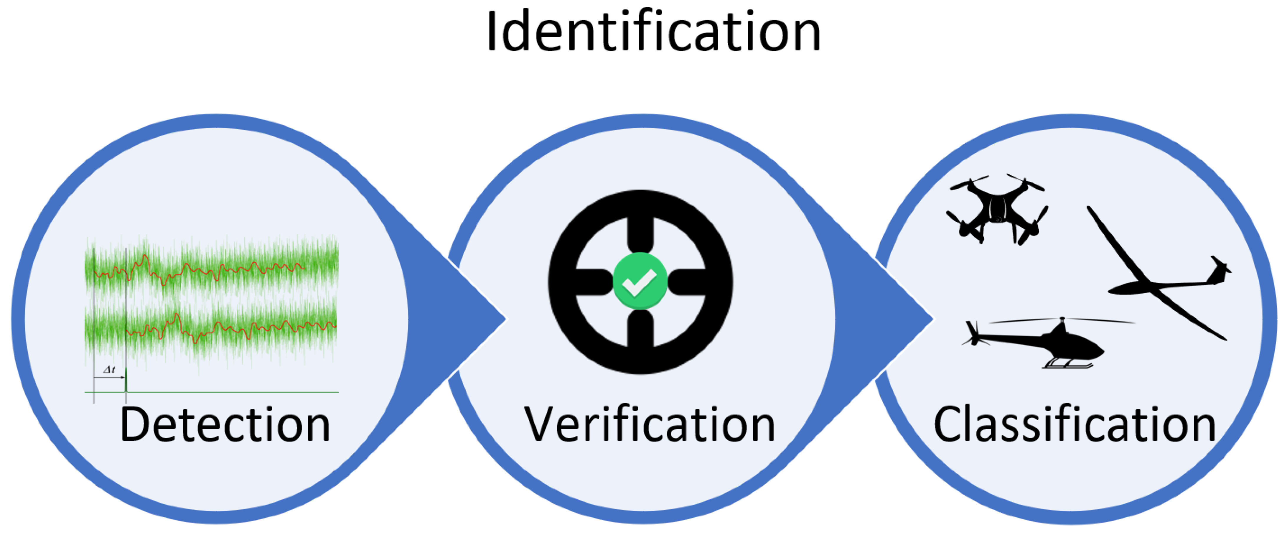
  • Video-based: Airspace monitoring using common visible spectrum cameras.
  • Sound-based: Monitoring the acoustic frequencies.
  • Radar-based: Using special purpose radar systems for drones.
  • Temperature-based: Tracing heat sources.
  • RF-based: Attempting to locate the radio frequencies the drones are transmitting towards their Ground Control Station (GCS), satellites, etc.
Each technique has its own advantages and disadvantages; for this reason, it is not uncommon for a combination of the above techniques to be used. When data from multiple sensors are being analyzed for the same purpose, this system is considered as a Multi-Sensor Fusion system [6]. This study relates exclusively to the radar-based technique, and the measurements are carried out using the RCS simulation software POFACETS (v.4.1). The exact methodology used is described analytically in the Section 2 of this study.
The majority of the published RCS research regarding small drones relates to multicopters; significantly fewer studies are focused on fixed-wing UAVs. Additionally, among those fixed-wing RCS studies, even fewer exist where fixed-wing UAVs with a wingspan of approximately 2 m are being analyzed. This trend is, of course, related to the growing popularity of the multicopter category. In the next paragraphs, a literature review regarding the RCS of small drones is outlined in order to establish the novelty of the current study.
Among the plethora of studies regarding multicopter vehicles, it is common to find papers that examine the RCS characteristics of a specific and well-known multirotor manufacturer’s model [7,8]. Few studies compare the RCS of various commercial multicopters [9,10], while there are many cases where the authors measure the RCS of their own designed multicopters [11,12,13,14,15]. Finally, there are fewer cases, such as [16], where multicopter swarm RCS is measured. The physical dimensions of the majority of these multicopters do not vary significantly, as a typical commercial multicopter distance between any of its electric motors to another is typically 20–40 cm. This factor alone is capable of limiting the RCS of these vehicles to a typical region of −10 to −20 dBsm.
In the above multirotor studies, despite the seemingly overlapping measurements that appear among some common commercial models, each one of the studies offers new findings that correlate to new measurement parameters, such as different radio frequency spectra, different look angle measurements, etc. These studies can be useful for future multicopter or radar designers. We consider that there is always room for expanding the RCS research, as the variables that participating in the RCS calculation are numerous, and each of them has a large number of possible values to consider; it is thus nearly impossible for a unique study to cover all the possible cases.
Regarding the fixed-wing UAVs’ RCS, as already mentioned, the available scientific references are limited. The situation in fixed-wing UAVs is even more complicated because of the large dispersion these vehicles present regarding their physical dimensions, as well as their aerodynamic design. Many possible designs appear for the fixed-wing UAVs, such as conventional designs, delta-wing, flying-wing, Blended Wing Body (BWB), etc.
In an effort to address this unevenness, Table 1 contains some fixed-wing RCS studies presenting greater complexity than the multirotor studies. These studies are sorted in descending order regarding aircraft wingspan.
It is obvious that the RCS values that these UAVs exhibit will differ greatly. An interesting study regarding the purposes of the current study is [23], where the authors explore the RCS values of some multicopters and a fixed-wing UAV, called the Pelikan Gamma 2100. This small UAV is of conventional design, as is the Euclid UAV which is being analyzed in the current study. Pelikan’s wingspan is 2.1 m in contrast with the 2 m of the Euclid, and its engine is mounted in the front (tractor), in contrast with the Euclid, which has its engine mounted in its aft main wing (pusher). Unfortunately, the authors in [23] do not offer many details regarding the RCS of the UAV, as they only present an RCS polar plot with a reference that the measurement was made at 9 Ghz, with the maximum RCS measured at 0.1 m2 (−10 dBsm) and mean RCS at 0.02 m2 (−16.99 dBsm). These values are compared to the corresponding values of the Euclid UAV in the Section 4 of the current study.
The importance and significance of this research lies to the fact that it offers new and analytical RCS information for a small fixed-wing UAV of a certain design and dimensions, which has not been studied before.
Current research findings do not cover all the possible cases in which readers would be interested. This fact is common with virtually any similar study that is aiming to explore the RCS signatures of any complex target. However, this research has taken into account realistic scenario conditions. Simulation parameters in scenario A are selected according to the real operational parameters of a common commercial anti-drone system. Furthermore, in scenario B, an attempt is made in order to announce a broader RCS perspective of the Euclid UAV, as we are simulating its RCS in the 3–16 Ghz spectrum.
The main purpose of this research is to establish valid and analytical RCS measurements, as well as conclusions for the small fixed-wing Euclid UAV, when the vehicle is the subject of illumination by the Robin radar system’s Elvira Anti Drone System. These findings can be used as a reference point for other similar type and size of fixed-wing UAVs, with the ulterior aim to protect infrastructure, hardware and people.
The secondary targets of this research are as follows:
  • The announcement of the Euclid UAV RCS results in the 3–16 Ghz spectrum.
  • The estimation of the Rmax distances in which the Elvira Anti Drone System will detect and classify the Euclid UAV.
Additionally, in this research, a hypothesis is being tested. Due to the relatively small flying altitude of such vehicles, the θ angle in which a drone radar will detect a target for the first time is expected to be a few degrees smaller than 90°. The Euclid UAV, as well as the majority of the fixed-wing aircrafts, present a small projected area in this θ angle range, due to the aerodynamic nature of their construction, despite their obviously larger overall dimensions they have in contrast with a typical multicopter. The Euclid UAV wingspan is 2 m, in contrast to the 45 cm distance between any two electric motors in the DJI Inspire 1 quadcopter. Given this, the hypothesis being tested is the following, H1:
H1. 
The fixed-wing Euclid UAV will exhibit smaller mean RCS values ( σ ¯ ) in the angle range φ = 0°–360° in comparison with the DJI Inspire 1 multicopter, when both are illuminated in the X band (8.7–9.65 Ghz), under θ = 85°.
As a brief presentation of the conclusions of this study, hypothesis H1 is proven to be valid, while Euclid UAV has σ ¯ = 17.6   dBsm , in contrast with σ ¯ = 9.7   dBsm for the DJI Inspire 1, for certain hypothesis H1 parameters. It is calculated that this difference in the mean RCS between the two vehicles can be translated for the Euclid UAV contrary to DJI Inspire 1, so as to be able to penetrate about 1 km closer to the Elvira Anti Drone System before being detected.
Similar differences in mean RCS of the two vehicles are observed also in the 3–16 GHz spectrum range. These findings come to strengthen even more the importance of this study, as the seemingly bulky, due to their large wingspan, fixed-wing UAVs may pose a bigger threat than a typical commercial multicopter under certain circumstances.

1.1. Radar Cross Section

Equation (1) represents the typical radar equation [24]:
P r = P t G t 4 π R 2 σ 4 π R 2 A e ,
where
P r : the power returned to the radar (Unit: W),
P t : the radiated power from the radar (Unit: W),
G t : the radar emitting antenna gain (Unit: Dimensionless),
R : the distance between the radar and the target (Unit: m),
σ : the Radar Cross Section (RCS) of the target (Unit: m2),
A e : the effective area of the receiving antenna (Unit: m2). A e = G t λ 2 4 π , where λ is the wavelength.
The first factor on the right of Equation (1) represents the power density, in a distance R, from a radar that transmits P t power using an antenna with a G t gain (Unit: W m 2 ).
The product of the two first factors on the right of Equation (1) represents the power per area unit, which returns to the radar’s receiving antenna. Such a receiving antenna with effective area A e will receive only a fraction of the overall returning to the radar power (Unit: W m 2 ).
If R m a x is the maximum distance a target can be, and S m i n is the minimum detectable signal, then we obtain Equation (2), which is known as the radar’s range equation [24]:
R m a x = P t G t A e σ ( 4 π ) 2   S m i n 4 ,
For the purposes of this study, Equation (2) will be useful for the calculation of the detection and classification distances of Euclid UAV, when it is illuminated by the Elvira Anti Drone System. If R m a x and σ values are known for a certain target, then any new R m a x value can be calculated for any different target with a new σ . P t , G t , A e   and   S m i n values remain intact, as they represent the constructive parameters for a given radar. By setting χ = P t G t A e ( 4 π ) 2   S m i n , we take the following simple Equation (3), in which x is a factor that represents all the internal constructive parameters of the radar (Unit: m2).
x = R 4 m a x σ ,
It is not easy to characterize a radar target by simply assigning an RCS value for all possible conditions, because RCS is a constantly alterable variable that its value depends, in any given time, on the radar look angles, frequency and polarization as well as the materials the target is made of [25,26]. For this reason, when a single RCS value is given in the literature for a target, an aircraft for instance, this RCS value is often a mean RCS value ( σ ¯ ) , which is calculated using a certain methodology each time. Many fighter aircrafts are designed in such a way to present their minimum RCS around their nose cone, because from this direction they will invade the enemy territory [27]. In Table 2, some estimations of the mean RCS of fighter aircrafts are presented [25]. In the last line, a typical living flying target, a bird, is present for comparison purposes.

1.2. Radars for Drones

As a result of this new form of threat generated from small drones, various companies have started to manufacture special-purpose radar systems for small targets. These targets are difficult identify because they present very small RCS values due to their small dimensions and the materials they are made of, which are usually dielectric materials. Finally, and contrary to a typical manned aircraft, small drones usually fly at low altitude and they can perform rapid maneuvers [28].
The operating principles of the transceiver element of an anti-drone system are the same as a conventional radar; the main difference an anti-drone system has with regard to a conventional radar lies in the sophisticated algorithms that help in the precise identification process. In addition, an anti-drone system may have provision for multiple sensor interconnection (Multi Sensor Fusion). Figure 1 illustrates the typical identification process of a drone-specific radar system.
During the detection phase, multiple hypotheses testing takes place in order to determine whether a target is present in the airspace or not. Afterwards, if an affirmative decision is made from the previous phase, the verification process is initiated. Verification is a process that aims to minimize false alarms before the system administrator is notified. A common check in this phase is to verify whether the target is really a human-made flying machine or just a bird. Finally, in the classification phase, and depending on each system’s capabilities, sophisticated signal processing algorithms are executed, in order to further classify the target. Some possible classification categories include the type of the object (multirotor, fixed-wing, helicopter), the number of the propulsion motors of the vehicle, the vehicle’s size, the type of the payload, etc. [29]. These classification techniques are a prominent and rapidly growing scientific field. For the most recent advances in this field, readers can refer to [30,31,32,33,34,35,36,37].
It is worth mentioning that, in recent years, the scientific community has tried to utilize some existing telecommunication technologies, with necessary modifications, in order to identify small drones. In the article [38], the authors explore the possibilities of utilizing weather radar for this purpose, while in article [39], 5G New Radio (NR) technology is proposed for the same purpose. The authors of [40] study drone identification using automotive radar sensors, and in [41], Long Term Evolution (LTE) and WiFi technologies are examined. Finally, study [42] proposes the use of marine radars.
To conclude this short literature review on the identification of drones by various identification devices, as well as the identification of various targets by the drones, in the next paragraph we present some prominent technologies that are being tested and that are expected to significantly contribute to the optimization of the speed and the accuracy of these procedures, as well as to the optimization of many other drone-related tasks.
Some state-of the-art technologies that were initially developed in the Artificial Intelligence (AI) scientific field are already present in the drone field and are being continuously improved. These technologies include Machine Learning (ML), as well as it’s correlated Deep Learning (DL) subcategory [43,44,45,46]. Another cutting-edge technology the drone field has borrowed from the computer networking field is the Internet of Things (IoT). The success of this technology in the drone field has led to the birth of the term Internet of Drones (IoD) [47,48].
For the current study, we chose to implement the simulations using the realistic operational parameters of a commercial anti-drone system. This system is called the Elvira Anti Drone System, and its manufacturing company is Robin radar systems. According to the technical specifications, which are available on the company’s website [49], the system has the following general characteristics (see Table 3).
Based on relevant coverage diagrams, which can be found in Elvira Anti Drone System’s technical specification documents, the following two diagrams were constructed (Figure 2 and Figure 3). In these figures, the main lobe of the system is illustrated for the detection phase (Figure 2) and also for the classification phase (Figure 3), both for the case of the DJI Inspire 1 quadcopter. These two diagrams are reconstructed in contrast with the prototypes, in order for the scale to be the same between the x and y axes. Furthermore, these reconstructed diagrams illustrate additional information, such as intermediate length markings, angle markings, etc.
By examining these diagrams, it can be stated that the target must fly at an altitude of 125 to 230 m for the detection and classification procedures to be carried out in the maximum possible distance. This flying altitude width is realistic for a small drone to fly at, and as shown in the diagrams, it corresponds to an elevation angle of 5° from the horizon, or a radar θ angle of 90–5 = 85°. Thus, all the simulations in this study were run with a θ = 85°.

1.3. Quadcopters RCS

As already stated, these small drones are a very difficult target to identify, even for the most sophisticated special-purpose radar systems. By recalling Elvira Anti Drone System’s specifications, for example, it is proven that the overall identification procedure of such small drones is a matter of a few kilometers, or even meters if the drone is very small.
Table 4 and Figure 4 present some RCS results of common multicopters. For the exact methodology according to which these RCS values were obtained, refer to the corresponding reference.
Some useful conclusions that can be extracted from Table 4 and Figure 4 are the following:
  • Frequencies of interest, when studying multicopter vehicles, are located within bands C, X, Ku and K according to the Institute of Electrical and Electronics Engineers (IEEE) [53].
  • The mean RCS value of DJI Inspire 1 are located in the −14.24 to −15 dBsm span, between two individual studies.
  • The RCS values of a typical multicopter are directly comparable to those of a bird. This conclusion suggests the importance of the effectiveness of the verification and classification algorithms running in a drone identification system, as conventional radar would probably reject these small targets.
  • A review of the physical dimensions specifications of each displayed drone uncovers a direct correlation between RCS and the volume of each drone.

2. Materials and Methods

In the following sub-sections, a step-by-step description of the methodology used is discussed.

2.1. Drones under Study

The two targets in this research consist of the Euclid fixed-wing UAV and DJI Inspire 1 quad copter. Some basic geometrical characteristics of each target are illustrated in Figure 5.
The Euclid small UAV is the aerial subsystem of the homonymous Euclid Unmanned Aerial System (UAS). The Euclid UAV is being developed by the General Department of National and Kapodistrian University of Athens. The system’s main roles include security, surveillance and reconnaissance applications. It has a wingspan of 2 m, and its fuselage length is 1.15 m. More information regarding the Euclid UAV can be obtained in [54]. In this research, DJI Inspire 1 is used exclusively for validation and comparison purposes. Furthermore, additional information regarding DJI Inspire 1 RCS values is presented in Table 4 for validation purposes. If the current study’s results for the DJI Inspire 1 are in the same region as the results in [51,52] for the same vehicle, then the Euclid UAV results’ validity is strengthened, because the same simulation methodology is used for both targets. Finally, by having a mean RCS value for the DJI Inspire 1 quadcopter, we can calculate Equation (3)’s x variable value, in order to estimate the Euclid UAV’s detection and classification distances using the Elvira Anti Drone System.

2.2. POFACETS Software

For the simulation of the RCS signatures, POFACETS (v.4.1) software was used. POFACETS code provides its own Graphical User Interface (GUI), and it can be executed through the MATLAB environment. POFACETS was developed by the US Naval Postgraduate School in order to estimate the RCS of complex geometry targets, using Physical Optics (PO) [55,56]. Any researcher can acquire the POFACETS code, free of charge, at [57]. Figure 6 illustrates the convention the software uses regarding the θ angle.
As can be observed, θ = 0° corresponds to an angle where the target is directly above the radar, while θ = 90° corresponds to an angle where the target is at the same plane as the radar. θ > 90° angles are used in situations where the target is at a lower altitude than the radar. Such situations include a setup where the radar is installed at a higher altitude, e.g., on top of a mountain, and the target is flying at a lower altitude, or when the radar is installed in an aircraft (e.g., an airborne radar).
POFACETS software is widely used by the scientific community, mainly for analyzing the RCS of flying targets. Some indicative references are presented here, where the software was used to study the RCS of fighter aircrafts [58,59], a 30 m wingspan flying wing [60], UAVs [61], low observable fighter aircraft (F-35) [62], as well as in a cruise missile study [63].
Finally, POFACETS code has recently inspired other researchers to expand its capabilities. The SARCASTIC project is one example [64]. In another study, [65], the authors managed to expand POFACETS capabilities in order to simulate Multiple Input Multiple Output (MIMO) radar topologies. MIMO radar systems are a very promising technology when it comes to drone detection, because a detection distance of 5 km was recently recorded for the DJI Phantom 4 quadcopter [66].

2.3. MeshLab Software

MeshLab is an open-source software for 3D mesh processing. Any researcher can download the software free of charge at [67]. MeshLab gives to its user the ability to perform various modifications easily and quickly for a 3D mesh, such as [68]:
  • Mesh cleaning, automatic filling of holes, duplicate or unreferenced vertices removal;
  • Remeshing according to the user preferences;
  • Mesh coloring, mesh inspection, etc.
MeshLab software is widely used for research purposes, in situations where any modification is required in a 3D object’s mesh. It has also been used by the scientific community in more specific studies, where the model was an aircraft or an aircraft’s subsystem [69,70,71,72]. For this study, v.2022.02 was used in order to manipulate targets’ meshes.

2.4. Simulation Prerequisites

Prior to the simulation parameters being imported into POFACETS software, the following prerequisite actions were carried out.

2.4.1. Models .stl Files Construction or Acquisition

POFACETS users can import a target’s geometry into the software using two possible modes. By using the first mode, the user can design the target’s geometry directly into the software by using the provided design tools. This mode, despite being useful for simple objects and for educational purposes, is not recommended for complex geometry targets such as an aircraft. The second mode the software provides is importing the .stl file of the target, which has been previously designed in another design software.
Both Euclid UAV and DJI Inspire 1 meshes were imported into POFACETS using .stl files. Euclid UAV geometry was obtained directly by its designing team, i.e., the current study’s authors, while DJI Inspire 1 geometry was obtained from www.grabcad.com [73], accessed on 14 September 2022. Inspire 1 was designed by Suifeng Liu, and it can be used for non-commercial public use if the acquisition webpage and the creator’s name are mentioned in the work [74]. This model has the ZENMUSE X5 camera, along with its gimbal, preinstalled. The authors of this research installed into the above DJI Inspire 1 model four 13.5” propellers designed by user jianghanmao of the same webpage www.grabcad.com [75], accessed on 14 September 2022.

2.4.2. Target Material Electrical Properties

As has already been mentioned in the introduction, in order for an accurate RCS simulation to be carried out, the researcher should know the electrical properties of the target’s materials. When studying small drones, either multicopters or small fixed-wing UAVs, the majority of the materials comprising these targets consist of dielectric materials. Table 5 contains the materials comprising the main structural objects of the two targets. Additionally, two more typical targets of the same category are presented: the small First Person View (FPV) Volantex Ranger aircraft and the small fixed-wing UAV RQ-11 Raven, manufactured by AeroVironment.
The only two electrical properties the POFACETS user is able to declare to the software regarding the materials are the relative permittivity, ε r (or dielectric constant), and the loss tangent, t a n δ , of the material.
Equation (4) correlates these two variables [80]. ε r and t a n δ values can slightly change when frequency and/or temperature changes [81].
ε r = ε ε 0 = ε j ε ε 0 = ε r j ε r = ε r ( 1 j   t a n δ ) ,
where
ε : the complex permittivity,
ε r : the relative complex permittivity,
ε 0 : the permittivity of free space ( 8.854 × 10 12   F / m ) ,
ε r : the real part of relative complex permittivity,
ε r : the imaginary part of relative complex permittivity,
t a n δ : dielectric loss tangent, and
δ : dielectric loss angle.
Table 6 contains some indicative values for the common materials that appear in Table 5.
Various strategies are followed by researchers when setting the electrical properties of a target consisting of multiple materials. Some researchers set into the simulation software different electrical property values for each of the main materials. Such a strategy is followed in [86], where the authors set certain electrical property values for the nose and the nozzle of an air-to-air missile, while they set different values for the fins, because they are made of different material. In [83], a specific pair of ε r and t a n δ values is used to describe the electrical properties of a wind turbine system. In addition, the authors of [63], use the default POFACETS values in their study, while in [39], the studied multicopter is considered to be manufactured by a Perfect Electric Conductor (PEC) material. For the purposes of the current study, the default values of POFACETS software for such purposes are considered for both targets. These values correspond to ε r   = 3.7 and t a n δ = 0.0045.

2.4.3. Proper Model Placing in POFACETS

In order for the RCS plots to be correctly represented, a proper placement of the target is needed within the triaxial reference system offered by the POFACETS software. The following correcting actions were made to the two targets, using the MeshLab software.
  • A check was made to verify that the scale of the targets corresponds to their correct dimensions in POFACETS. It was found that the dimensions were wrongly displayed, enlarged by a factor of 103. The scale of both targets was fixed in MeshLab software.
  • In order for the POFACETS software to display the RCS of the target’s nose at φ = 0°, the model must be placed exactly as displayed in Figure 7 [63]. Consecutive rotate commands and the center command were used in MeshLab software for the proper placing of both targets.
  • The last preliminary action was to check both targets for their normal surface’s direction, a type of check that is referred to simply as a “check for normal”. By conducting this type of check, it can be determined whether the mesh of the target is designed with the correct direction or not. Every facet within a mesh has two sides: the front and back side. In order for the POFACETS software to be able to calculate the scattered radiation correctly, all target facets must be designed in such a way where the front side is the one that is in touch with the model’s surrounding space (that is, with the atmosphere in a real model). MeshLab software can visualize each facet’s direction with small line segments, as Figure 8 illustrates for the Euclid UAV. Each line segment that has a direction from the aircraft’s skin towards the surrounding space indicates a properly placed surface.
It is worth mentioning that in the areas where many line segments are concentrated, the aircraft’s geometry is complex. These areas are located mainly around the winglets and around the motor and propeller of the Euclid UAV.

2.5. Simulation Parameters

For this study, two discrete scenarios were simulated, as indicated in Table 7. Both targets (Euclid UAV and DJI Inspire) are examined in both scenarios. The common simulation parameters between the two scenarios were the radar type (monostatic), the θ angle (85°), the electrical properties of the target’s materials and the radar polarization (Theta TM-z). Shifting the radar polarization to Theta TE-z did not seemed to affect the RCS results notably.
The first scenario aims to replicate the illumination of the two targets using the realistic parameters of the Elvira Anti Drone System. This is the reason the θ angle was set at 85° and these three radar frequencies were chosen. The first frequency (8.7 Ghz) corresponds to the lower frequency of the Elvira Anti Drone System. The second frequency (9.175 Ghz) corresponds to the center frequency of the system, and the third frequency (9.65 Ghz) corresponds to the system’s upper frequency. The φ angle for this scenario is set to cover the entire possible angle range (0°–360°), with a 1° step. By using this choice, we can offer full RCS results in polar plots for each one of the vehicles.
The second scenario aims to record the implications that the frequency change has for the RCS of the two targets. Smaller frequencies and larger frequencies than the Elvira Anti Drone System are studied. The simulation frequency range was set at 3 to 16 GHz, using 100 MHz increments. The θ angle is also set at 85° for this scenario. Regarding the φ angle, a typical angle of 45° was chosen in order to exclude any RCS spikes, which usually appear at φ = 0, 90, 180 and 270 degrees.
Figure 9 illustrates the simulation parameters for each one of the scenarios.

3. Results

In the following section, the RCS results for the two targets are presented. Among the results of this research, a mean RCS value ( σ ¯ ) is given, which corresponds to the mean value the RCS in the specific φ angle width or in the specific frequency width studied. In the following results plots, the mean RCS values are marked with a dashed line segment of red color.

3.1. Scenario A Results

In the following sections, the RCS results of the two targets for scenario A are presented and discussed.

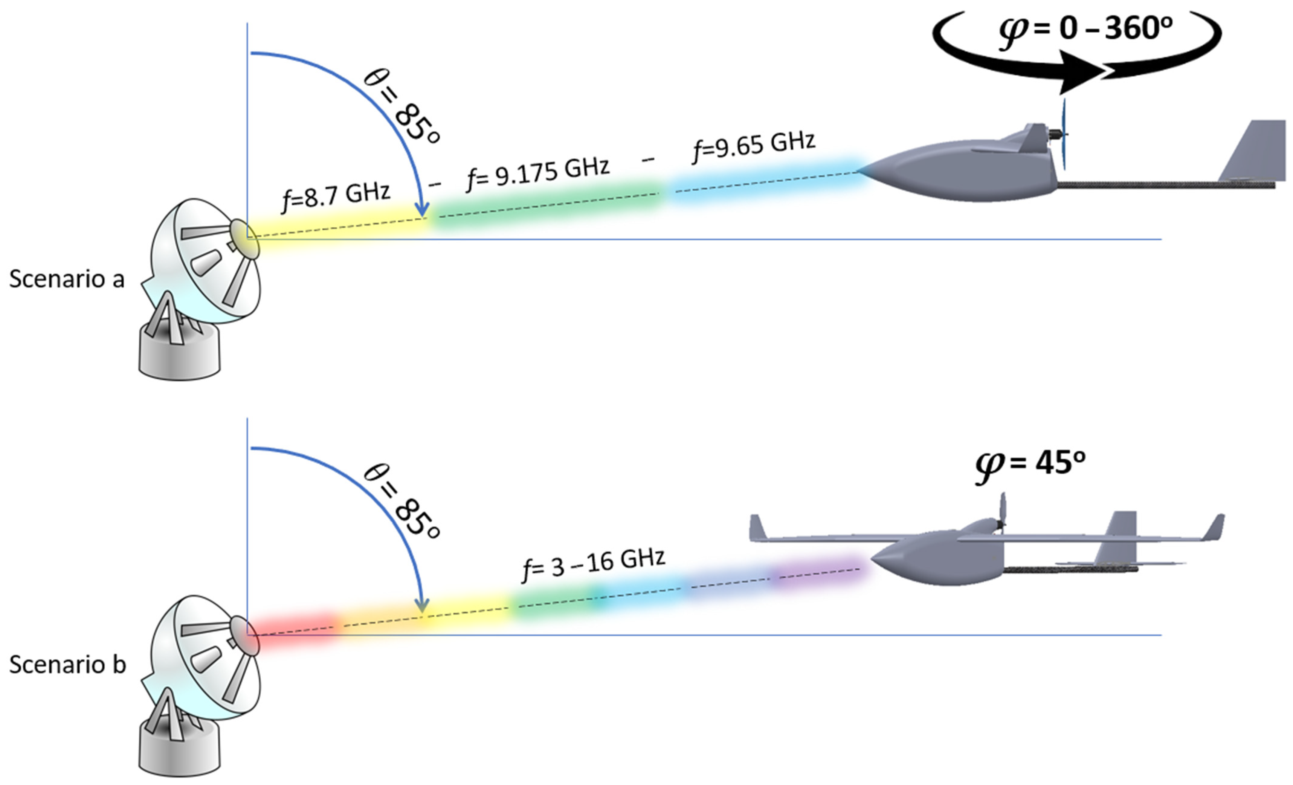
3.1.1. Results for θ = 85°, φ = 0–360°, f = 8.7 Ghz

Figure 10 presents the RCS results of the DJI Inspire 1, while Figure 11 presents the RCS results of the Euclid UAV. Measurement parameters are θ = 85°, φ = 0°–360° and f = 8.7 Ghz.

3.1.2. Results for θ = 85°, φ = 0–360°, f = 9.175 Ghz

Figure 12 presents the RCS results of the DJI Inspire 1, while Figure 13 presents the RCS results of the Euclid UAV. Measurement parameters are θ = 85°, φ = 0°–360° and f = 9.175 Ghz.

3.1.3. Results for θ = 85°, φ = 0–360°, f = 9.65 Ghz

Figure 14 presents the RCS results of the DJI Inspire 1, while Figure 15 presents the RCS results of the Euclid UAV. Measurement parameters are θ = 85°, φ = 0°–360° and f = 9.65 Ghz.

3.1.4. Synopsis and Discussion of the Scenario A Results

Table 8 contains the mean RCS values of the two targets for each one of the three radar frequencies.
The conclusions from the Scenario A simulation results are the following:
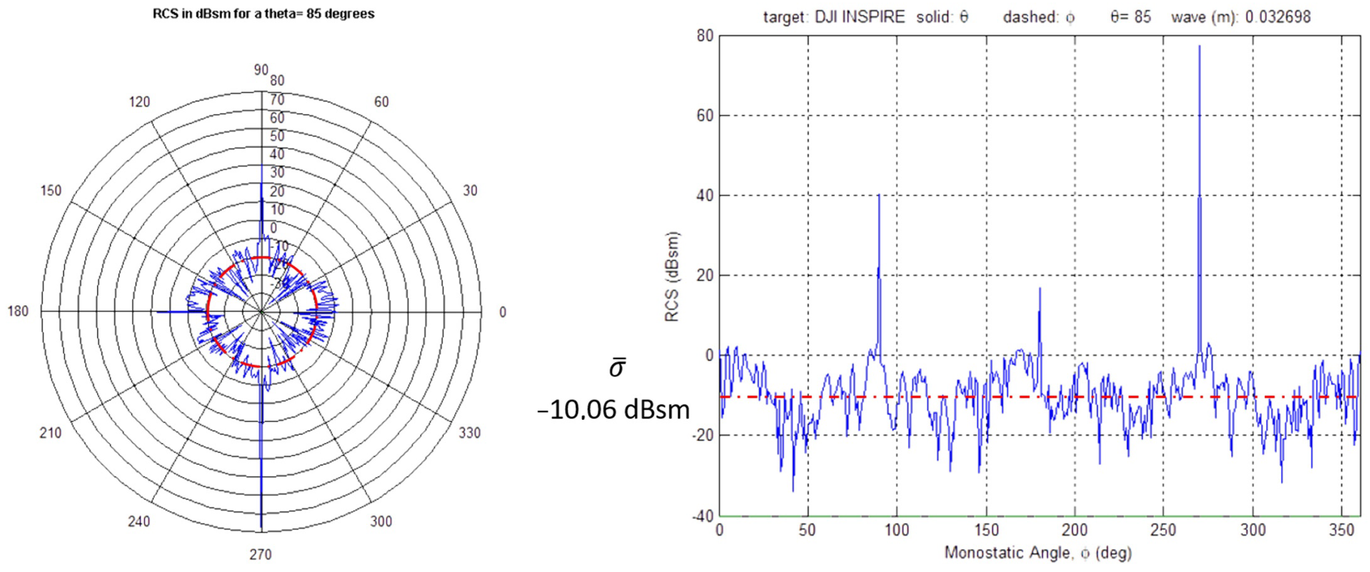
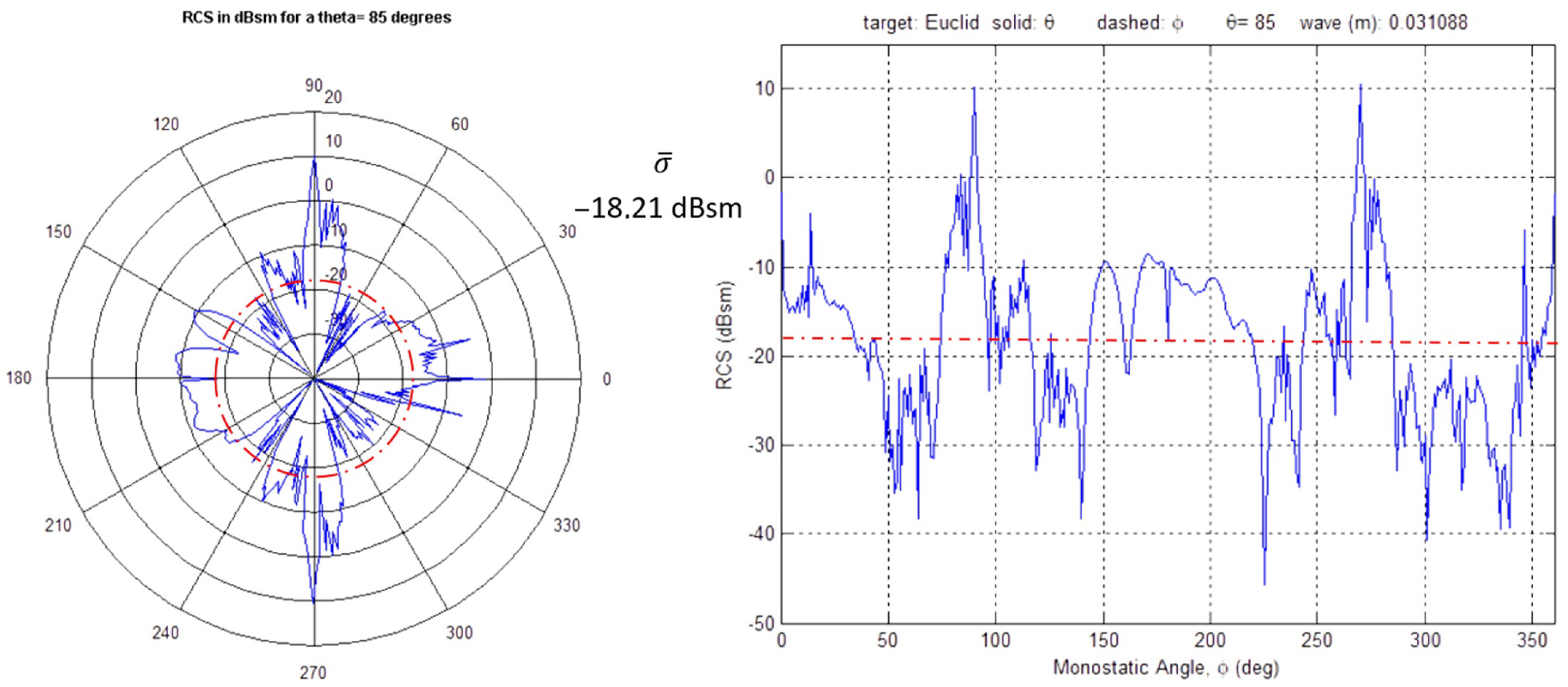
  • The width in which the DJI Inspire 1 mean RCS is located is −9.29 to −10.06 dBsm. The corresponding width of the Euclid UAV is −16.96 to −18.21 dBsm. Given this, it can be concluded that, regarding these specific viewing angles and frequencies, the Euclid UAV is a harder target to be identified compared to the DJI Inspire 1. This statement confirms the H1 hypothesis stated in the introduction of this study.
  • The Euclid UAV presents increased mean RCS values at φ = 90° and φ = 270° angles. These angles represent the aircraft’s wings. Contrarily, small mean RCS values are observed near the aircraft’s nose. This means that the identification of the Euclid UAV would be even harder using the Elvira Anti Drone System, when the aircraft directly approaches the radar system.
  • The DJI Inspire 1 quadcopter presents nearly symmetric RCS signatures throughout the φ = 0°–360° circle. Some spikes appear at φ = 90° and φ = 270°. This symmetric signature is correlated with the nearly symmetric geometry of the target itself. This means that DJI Inspire 1 RCS is independent from the φ angle when the vehicle is approaching the radar.

3.2. Scenario B Results (θ = 85°, φ = 45°, f = 3–16 Ghz)

Figure 16 presents the DJI Inspire 1 RCS results, while Figure 17 presents the Euclid UAV RCS results. Measurement parameters are θ = 85° and φ = 45° within the 3 to 16 Ghz spectrum.
The conclusions from the Scenario B simulation results are the following:
  • The mean RCS values of both targets within the 3 to 16 GHz spectrum are about 5 dBsm smaller compared to their corresponding values within the 8.7 to 9.65 GHz spectrum of Scenario A.
  • DJI Inspire 1 RCS presents relatively large fluctuations. Peak to peak absolute values of these fluctuations can reach 20 dBsm for θ = 85° and φ = 45° within the 3 to 16 Ghz spectrum. However, the amplitude of the fluctuations seems to be constant throughout the whole simulation spectrum.
  • It can be stated that the Euclid UAV RCS is higher in the region of 3 to 12 GHz, and it decreases in the region of 12 to 16 GHz. As a result, the Euclid UAV would be less visible to radars that operate at the Ku band. The absolute value of the fluctuation’s amplitude within each of these regions is about 10 dBsm, expressively smaller than the DJI Inspire.
  • Mean RCS Values ( σ ¯ ) for this scenario are 13.92 dBsm for the DJI Inspire and −22.77 dBsm for the Euclid UAV.
  • This scenario’s results for the DJI Inspire 1 are strongly correlated with the results of other researchers [51,52], computed for the same vehicle (about −14 dBsm). Given this, it is safe to announce the Euclid UAV RCS results.
  • Aside from Scenario A, Scenario B also confirms the H1 hypothesis, which was stated in the introduction of this study.

3.3. Euclid UAV Detection and Classification Range Estimation

In this section, a range estimation is attempted for the Euclid UAV by the Elvira Anti Drone System, both for the detection and for the classification phases. The θ angle for the range estimation is 85°, and the mean RCS values of both targets were used for the Elvira Anti Drone System’s central frequency of 9.175 GHz. Table 9 contains the range estimation results for the Euclid UAV. Note that the DJI Inspire 1 corresponding ranges are given by the Elvira Anti Drone System manufacturer.
The value of the Equation (3) × variable is calculated as equal to 5.95202 × 10 14   ( m 2 ) for the detection phase and equal to 8.19276 × 10 13   ( m 2 ) for the classification phase of the Elvira Anti Drone System.
It is noted that the Euclid UAV could penetrate about 1 km closer to the Elvira Anti Drone System, before its detection, compared to the DJI Inspire 1.

4. Discussion

From the study findings, it is observed that the Euclid fixed-wing UAV with a wingspan of 2 m is more difficult to identify by a commercial radar for drones, compared to a typical quadcopter such as the DJI Inspire 1, whose physical dimensions are much smaller, when both are flying at a low altitude where the radar θ angle is 85°. This study’s calculations revealed that the Euclid UAV could penetrate about 1 km closer to the Elvira Anti Drone System before its detection compared to the DJI Inspire 1, as the Euclid UAV can reach a distance of 1784 m from the Elvira Anti Drone system, while the DJI Inspire 1 is detected at a distance of 2768 m.
The mean RCS value ( σ ¯ ) for the Euclid UAV was computed to be −17.69 dBsm for the Elvira Anti Drone System’s central frequency, which is 9.175 GHz. This value is strongly correlated to the mean RCS value of −16.99 dBsm given in [23] for a similar fixed-wing plane, called the Pelikan Gamma 2100, with a wingspan of 2.1 m, at f = 9 GHz. In order to strengthen the validity of the detailed Euclid UAV results of this research, the DJI Inspire 1 quadcopter was used as validation tool. Additionally, the simulated mean RCS values of the DJI Inspire 1 in this study are strongly correlated to the values that other studies give for the same vehicle, which is about −14 dBsm at the 3 to 16 GHz spectrum. In the same 3 to 16 GHz spectrum, the Euclid UAV presents a mean RCS value of −22.77 dBsm, in contrast with −13.92 dBsm of the DJI Inspire 1, under θ = 85° and φ = 45°. Higher RCS values are observed for the Euclid UAV near its main wing, at φ = 90° and φ = 270°. A value lower than the mean RCS is observed at the Euclid’s nose. Given this, it can be stated that the Euclid UAVs identification would be even harder when the aircraft is heading directly towards the radar.
The reader of this research can benefit from the Euclid UAV RCS analytical measurements, which are presented in the study’s numerous plots. Such analytical results for this kind of a fixed-wing UAV are presented for the first time in the scientific literature, and they can be used as a reference point for the study of the RCS of similar vehicles.
The beyond-the-scope implications of this research consist mainly of human and infrastructure safety aspects with regard to small fixed-wing UAVs, which constructively and commercially have been superseded by multicopters. We hope that this study’s findings can be used in this direction and not to constitute a springboard for the further deliberation of RCS reduction of these flying vehicles.
The analytical structure used in this study enables it to be scalable for future work on vehicles similar to Euclid small aerial vehicles. The Section 2 contains the parameter values and techniques used, in order for this research to be easily expanded. Possible extensions of this study on the RCS of small fixed-wing UAVs could mainly include the following scenarios:
  • Study of different aerodynamic designs of small aerial vehicles, such as small flying wings, blended wing body vehicles, etc.
  • Study of the above vehicles in different frequency widths than other commercial anti drone systems than the Elvira Anti Drone System.
Research that studies the RCS of any target has many limitations by nature, because of the number of participating variables, with each variable having a large value range. This study is limited to the 3–16 GHz range, and the studied θ angle was set at 85°, due to the fact that this angle was found to be the most plausible angle for a low-flying drone to be detected, according to commercial anti-drone system coverage diagrams. Furthermore, this study assumes that the material of the two targets that are being simulated is a dielectric with ε r   = 3.7 and t a n δ = 0.0045. These are the default values of the POFACETS software for such occasions. Finally, a limitation is present in all POFACETS software simulations, where the propellers of the objects under study are stationary, and they cannot rotate during the simulation. Despite these limitations, this study’s results regarding the validation vehicle DJI Inspire 1 are in excellent accordance with other studies’ results for the same vehicle.
Regarding the limitations of this work in practical applications, it can be stated that the main limitation originates from the fact that this research mainly studies a certain pair of radar-UAVs. Despite the fact that the possibilities for the Euclid UAV facing the Elvira Anti Drone System in the real world are limited, we consider that the conclusions generated from this research are a valuable reference base for the generic small fixed-wing UAVs, with a wingspan of about 2 m, which are of a conventional aerodynamic design.
Additionally, this research, as well as every other study of RCS signatures, has limitations in its practical use that originate from the statistical nature of the RCS variable by itself [23] and also from the real capabilities of the radar’s software to transition from the detection phase to the verification phase and then to the classification phase (if this capability is present).

Author Contributions

Conceptualization, I.K.K.; methodology, A.H.; validation, A.K.B.; formal analysis, E.S.V.; investigation, J.C.S.; resources, J.C.S.; writing—original draft preparation, E.S.V.; writing—review and editing, A.K.B.; supervision, A.H.; project administration, I.K.K. All authors have read and agreed to the published version of the manuscript.

Funding

This research received no external funding.

Institutional Review Board Statement

Not applicable.

Informed Consent Statement

Not applicable.

Data Availability Statement

Numerical data can be found in tables and figures in the current article.

Conflicts of Interest

The authors declare no conflict of interest.

Abbreviations

The following abbreviations are used in this manuscript:
5GFifth Generation
AIArtificial Intelligence
BWBBlended Wing Body
CRPCarbon-Reinforced Plastics
DLDeep Learning
EPOExpanded PolyOlefin
FPVFirst Person View
FRPFiber-Reinforced Plastics
GCSGround Control Station
HDPEHigh-Density PolyEthylene
IEEEInstitute of Electrical and Electronics Engineers
IoTInternet of Tings
IoDInternet of Drones
LDPELow-Density PolyEthylene
LLDPELinear Low-Density PolyEthylene
LTELong-Term Evolution
LW-PLALightWeight PolyLactic Acid
MIMOMultiple Input Multiple Output
MLMachine Learning
NRNew Radio
PECPerfect Electric Conductor
PLAPolyLactic Acid
POPhysical Optics
PPPolyPropylene
RCSRadar Cross-Section
TPVThermoPlastic Vulcanizates
UASUnmanned Aerial System
UAVUnmanned Aerial Vehicle
VTOLVertical Take-Off and Landing

References

  1. Kardasz, P.; Doskocz, J. Drones and Possibilities of Their Using. J. Civ. Env. Eng. 2016, 6, 1–7. [Google Scholar] [CrossRef]
  2. Rohling, H. (Ed.) 2017 18th International Radar Symposium (IRS): 28–30 June 2017; Cuvillier Verlag: Göttingen, Germany, 2017; ISBN 978-1-5090-4312-5. [Google Scholar]
  3. Wild, G.; Murray, J.; Baxter, G. Exploring Civil Drone Accidents and Incidents to Help Prevent Potential Air Disasters. Aerospace 2016, 3, 22. [Google Scholar] [CrossRef] [Green Version]
  4. Shvetsova, S.; Shvetsov, A. Safety When Flying Unmanned Aerial Vehicles at Transport Infrastructure Facilities. Transp. Res. Procedia 2021, 54, 397–403. [Google Scholar] [CrossRef]
  5. Bisio, I.; Garibotto, C.; Lavagetto, F.; Sciarrone, A.; Zappatore, S. Unauthorized Amateur UAV Detection Based on WiFi Statistical Fingerprint Analysis. IEEE Commun. Mag. 2018, 56, 106–111. [Google Scholar] [CrossRef]
  6. Samaras, S.; Diamantidou, E.; Ataloglou, D.; Sakellariou, N.; Vafeiadis, A.; Magoulianitis, V.; Lalas, A.; Dimou, A.; Zarpalas, D.; Votis, K.; et al. Deep Learning on Multi Sensor Data for Counter UAV Applications—A Systematic Review. Sensors 2019, 19, 4837. [Google Scholar] [CrossRef] [Green Version]
  7. Guo, M.; Lin, Y.; Sun, Z.; Fu, Y. Research on Monostatic Radar Cross Section Simulation of Small Unmanned Aerial Vehicles. In Proceedings of the 2018 International Conference on Microwave and Millimeter Wave Technology (ICMMT2018), Chengdu, China, 7–11 May 2018. [Google Scholar]
  8. Schneebeli, M.; Leuenberger, A.; Wabeke, L.; Kloke, K.; Kitching, C.; Siegenthaler, U.; Wellig, P. Drone Detection with a Multistatic C-Band Radar. In Proceedings of the 2021 21st International Radar Symposium (IRS), Berlin, Germany, 21 June 2021; pp. 1–10. [Google Scholar]
  9. Ezuma, M.; Anjinappa, C.K.; Semkin, V.; Guvenc, I. Comparative Analysis of Radar Cross Section Based UAV Classification Techniques. arXiv 2021, arXiv:2112.09774. [Google Scholar]
  10. Ezuma, M.; Anjinappa, C.K.; Funderburk, M.; Guvenc, I. Radar Cross Section Based Statistical Recognition of UAVs at Microwave Frequencies. IEEE Trans. Aerosp. Electron. Syst. 2022, 58, 27–46. [Google Scholar] [CrossRef]
  11. Semkin, V.; Yin, M.; Hu, Y.; Mezzavilla, M.; Rangan, S. Drone Detection and Classification Based on Radar Cross Section Signatures. In Proceedings of the 2020 International Symposium on Antennas and Propagation (ISAP), Osaka, Japan, 25 January 2021; pp. 223–224. [Google Scholar]
  12. Petrovic, P.Z.; Savic, S.V.; Ilic, M.M. Electromagnetic Modelling of Micro-Doppler Signatures of Commercial Airborne Drones. In Proceedings of the 2021 29th Telecommunications Forum (TELFOR), Belgrade, Serbia, 23 November 2021; pp. 1–4. [Google Scholar]
  13. Max Chung, S.S.; Tuan, S.-C. Changing the Radar Cross Section of Quadcopter by Shape Modification. In Proceedings of the 2021 IEEE Asia-Pacific Microwave Conference (APMC), Brisbane, Australia, 28 November 2021; pp. 350–352. [Google Scholar]
  14. Unalir, D.; Sezgin, S.; Yuva, C.S.; Gokdogan, B.Y.; Aydin, E. Low Radar Cross Section UAV Design in X-Band. In Proceedings of the 2022 30th Signal Processing and Communications Applications Conference (SIU), Safranbolu, Turkey, 15 May 2022; pp. 1–4. [Google Scholar]
  15. Chung, S.S.M.; Tuan, S.-C. Frequency and Incident Angle Effects on Radar Cross Section of Quadcopter Unmanned Aerial Vehicle. In Proceedings of the 2021 Photonics & Electromagnetics Research Symposium (PIERS), Hangzhou, China, 21 November 2021; pp. 2173–2177. [Google Scholar]
  16. Cai, K.-C.; Liao, C.-T.; Chen, C.-H.; Chen, H.-M. Study on Radar Cross-Section Characteristics of Quadrocopter Group Flight. In Proceedings of the 2021 International Symposium on Antennas and Propagation (ISAP), Taipei, Taiwan, 19 October 2021; pp. 1–2. [Google Scholar]
  17. Xiaoxiao, H. Study on Radar Cross Section for Flying-Wing Unmanned Aerial Vehicle with Close Formation Flight. In Proceedings of the 31st Congress of the International Council of the Aeronautical Sciences (ICAS), Belo Horizonte, Brazil, 9–14 September 2018; pp. 1–5. [Google Scholar]
  18. ÖzdemİR, C. Radar cross Section Analysis of Unmanned Aerial Vehicles Using Predics. Int. J. Eng. Geosci. 2020, 5, 144–149. [Google Scholar] [CrossRef]
  19. Sadraey, M.H. Design of Unmanned Aerial Systems; Aerospace series; John Wiley & Sons: Hoboken, NJ, USA, 2020; ISBN 978-1-119-50862-5. [Google Scholar]
  20. Ryapolov, I.; Sukharevsky, O.; Vasilets, V. Radar Cross-Section Calculation for Unmanned Aerial Vehicle. In Proceedings of the 2014 International Conference on Mathematical Methods in Electromagnetic Theory, Dnipropetrovsk, Ukraine, 26–28 August 2014; pp. 258–261. [Google Scholar]
  21. Gong, J.; Li, D.; Yan, J.; Hu, H.; Kong, D. Comparison of Radar Signatures from a Hybrid VTOL Fixed-Wing Drone and Quad-Rotor Drone. Drones 2022, 6, 110. [Google Scholar] [CrossRef]
  22. Yang, Y.; Wang, X.-S.; Xiao, S.-P.; Li, Y.-Z.; Shi, L.-F. Experimental Analysis of Fully Polarimetric Radar Cross Section of Fixed-Wing UAV. In Proceedings of the 2019 PhotonIcs & Electromagnetics Research Symposium-Spring (PIERS-Spring), Rome, Italy, 17–20 June 2019; pp. 1354–1358. [Google Scholar]
  23. Sedivy, P.; Nemec, O. Drone RCS Statistical Behaviour. In Proceedings of the MSG-SET-183 Specialists’ Meeting on “Drone Detectability: Modelling the Relevant Signature”, North Atlantic Treaty Organization (NATO), Held Virtually (via WebEx), 27 April 2021; pp. 4-1–4-18. [Google Scholar]
  24. Skolnik, M.I. (Ed.) Radar Handbook, 3rd ed.; McGraw-Hill: New York, NY, USA, 2008; ISBN 978-0-07-148547-0. [Google Scholar]
  25. Fourikis, N. Advanced Array Systems, Applications and RF Technologies; Signal Processing and Its Applications; Academic Press: San Diego, CA, USA, 2000; ISBN 978-0-12-262942-6. [Google Scholar]
  26. Leung, S.; Liang, C.; Tao, X.; Li, F.; Poo, Y.; Wu, R. Broadband Radar Cross Section Reduction by an Absorptive Metasurface Based on a Magnetic Absorbing Material. Opt. Express 2021, 29, 33536. [Google Scholar] [CrossRef]
  27. Yue, K.; Chen, S.; Shu, C. Calculation of Aircraft Target’s Single-Pulse Detection Probability. J.Aerosp. Technol. Manag. 2015, 7, 314–322. [Google Scholar] [CrossRef]
  28. Ezuma, M.; Ozdemir, O.; Anjinappa, C.K.; Gulzar, W.A.; Guvenc, I. Micro-UAV Detection with a Low-Grazing Angle Millimeter Wave Radar. In Proceedings of the 2019 IEEE Radio and Wireless Symposium (RWS), Orlando, FL, USA, 20–23 January 2019; pp. 1–4. [Google Scholar]
  29. Coluccia, A.; Parisi, G.; Fascista, A. Detection and Classification of Multirotor Drones in Radar Sensor Networks: A Review. Sensors 2020, 20, 4172. [Google Scholar] [CrossRef] [PubMed]
  30. Fu, R.; Al-Absi, M.A.; Kim, K.-H.; Lee, Y.-S.; Al-Absi, A.A.; Lee, H.-J. Deep Learning-Based Drone Classification Using Radar Cross Section Signatures at MmWave Frequencies. IEEE Access 2021, 9, 161431–161444. [Google Scholar] [CrossRef]
  31. Sayed, A.N.; Riad, M.M.Y.R.; Ramahi, O.M.; Shaker, G. UAV Classification Using Neural Networks and CAD-Generated Radar Datasets. TechRxiv 2022. [Google Scholar] [CrossRef]
  32. De Wit, J.J.M.; Gusland, D.; Trommel, R.P. Radar Measurements for the Assessment of Features for Drone Characterization. In Proceedings of the 2020 17th European Radar Conference (EuRAD), Utrecht, The Netherlands, 10 January 2021; pp. 38–41. [Google Scholar]
  33. Ye, L.; Hu, S.; Yan, T.; Xie, Y. GAF Representation of Millimeter Wave Drone RCS and Drone Classification Method Based On Deep Fusion Network Using ResNet. In IEEE Transactions on Aerospace and Electronic Systems; IEEE: New York, NY, USA, 2022; pp. 1–11. [Google Scholar] [CrossRef]
  34. Raval, D.; Hunter, E.; Hudson, S.; Damini, A.; Balaji, B. Convolutional Neural Networks for Classification of Drones Using Radars. Drones 2021, 5, 149. [Google Scholar] [CrossRef]
  35. Roychowdhury, S.; Ghosh, D. Machine Learning Based Classification of Radar Signatures of Drones. In Proceedings of the 2021 2nd International Conference on Range Technology (ICORT), Balasore, India, 5 August 2021; pp. 1–5. [Google Scholar]
  36. Dale, H.; Baker, C.; Antoniou, M.; Jahangir, M.; Atkinson, G.; Harman, S. SNR-dependent Drone Classification Using Convolutional Neural Networks. IET Radar Sonar Navi 2022, 16, 22–33. [Google Scholar] [CrossRef]
  37. Ciattaglia, G.; Senigagliesi, L.; Alidori, D.; Cipriani, L.; Iadarola, G.; Spinsante, S.; Gambi, E. Drone Classification Using MmWave Micro-Doppler Radar Measurements. In Proceedings of the 2022 IEEE 9th International Workshop on Metrology for AeroSpace (MetroAeroSpace), Pisa, Italy, 27 June 2022; pp. 259–264. [Google Scholar]
  38. Blake, W.; Burger, I. Small Drone Detection Using Airborne Weather Radar. In Proceedings of the 2021 IEEE Radar Conference (RadarConf21), Atlanta, GA, USA, 7 May 2021; pp. 1–4. [Google Scholar]
  39. Semkin, V.; Haarla, J.; Pairon, T.; Slezak, C.; Rangan, S.; Viikari, V.; Oestges, C. Analyzing Radar Cross Section Signatures of Diverse Drone Models at MmWave Frequencies. IEEE Access 2020, 8, 48958–48969. [Google Scholar] [CrossRef]
  40. Morris, P.J.B.; Hari, K.V.S. Detection and Localization of Unmanned Aircraft Systems Using Millimeter-Wave Automotive Radar Sensors. IEEE Sens. Lett. 2021, 5, 1–4. [Google Scholar] [CrossRef]
  41. Sun, M.; Guo, Z.; Li, M.; Gerdes, R. Passive Drone Localization Using LTE Signals. In Proceedings of the 15th ACM Conference on Security and Privacy in Wireless and Mobile Networks, San Antonio, TX, USA, 16 May 2022; pp. 295–297. [Google Scholar]
  42. Rudys, S.; Ragulis, P.; Laučys, A.; Bručas, D.; Pomarnacki, R.; Plonis, D. Investigation of UAV Detection by Different Solid-State Marine Radars. Electronics 2022, 11, 2502. [Google Scholar] [CrossRef]
  43. Li, Y.; Wei, X.; Li, Y.; Dong, Z.; Shahidehpour, M. Detection of False Data Injection Attacks in Smart Grid: A Secure Federated Deep Learning Approach. IEEE Trans. Smart Grid 2022, 13, 4862–4872. [Google Scholar] [CrossRef]
  44. Dadrass Javan, F.; Samadzadegan, F.; Gholamshahi, M.; Ashatari Mahini, F. A Modified YOLOv4 Deep Learning Network for Vision-Based UAV Recognition. Drones 2022, 6, 160. [Google Scholar] [CrossRef]
  45. Toma, C.; Popa, M.; Iancu, B.; Doinea, M.; Pascu, A.; Ioan-Dutescu, F. Edge Machine Learning for the Automated Decision and Visual Computing of the Robots, IoT Embedded Devices or UAV-Drones. Electronics 2022, 11, 3507. [Google Scholar] [CrossRef]
  46. Tran, T.L.C.; Huang, Z.-C.; Tseng, K.-H.; Chou, P.-H. Detection of Bottle Marine Debris Using Unmanned Aerial Vehicles and Machine Learning Techniques. Drones 2022, 6, 401. [Google Scholar] [CrossRef]
  47. Heidari, A.; Jabraeil Jamali, M.A. Internet of Things Intrusion Detection Systems: A Comprehensive Review and Future Directions. Clust. Comput 2022, 1–28. [Google Scholar] [CrossRef]
  48. Heidari, A.; Navimipour, N.J.; Unal, M.; Zhang, G. Machine Learning Applications in Internet-of-Drones: Systematic Review, Recent Deployments, and Open Issues. ACM Comput. Surv. 2022, 3571728. [Google Scholar] [CrossRef]
  49. Systems, R.R. Drone Detection Radar|ELVIRA|Robin Radar. Available online: https://www.robinradar.com/elvira-datasheet (accessed on 29 August 2022).
  50. Patel, J.S.; Fioranelli, F.; Anderson, D. Review of Radar Classification and RCS Characterisation Techniques for Small UAVs or Drones. IET Radar Sonar Amp Navig. 2018, 12, 911–919. [Google Scholar] [CrossRef]
  51. Ezuma, M.; Funderburk, M.; Guvenc, I. Compact-Range RCS Measurements and Modeling of Small Drones at 15 GHz and 25 GHz. In Proceedings of the 2020 IEEE Radio and Wireless Symposium (RWS), San Antonio, TX, USA, 26–29 January 2020. [Google Scholar]
  52. Salim, I.M.; Barbary, M.; Abd El-azeem, M.H. Novel Bayesian Track-Before-Detection for Drones Based VB-Multi-Bernoulli Filter and a GIGM Implementation. Radioengineering 2020, 29, 397–404. [Google Scholar] [CrossRef]
  53. Ruiz-Perez, F.; López-Estrada, S.M.; Tolentino-Hernández, R.V.; Caballero-Briones, F. Carbon-Based Radar Absorbing Materials: A Critical Review. J. Sci. Adv. Mater. Devices 2022, 7, 100454. [Google Scholar] [CrossRef]
  54. Kapoulas, I.K.; Statharas, J.C.; Hatziefremidis, A.; Baldoukas, A.K. Fast Airfoil Selection Methodology for Small Unmanned Aerial Vehicles. Appl. Sci. 2022, 12, 9328. [Google Scholar] [CrossRef]
  55. Garrido, E.; Jenn, D. A MATLAB Physical Optics RCS Prediction Code. ACES Newsl. 2000, 15, 7–12. [Google Scholar]
  56. Jenn, D.C. Radar and Laser Cross Section Engineering, 2nd ed.; AIAA Education Series; American Institute of Aeronautics and Astronautics: Reston, VA, USA, 2005; ISBN 978-1-56347-702-7. [Google Scholar]
  57. Jenn, D. POFACETS4.1. Available online: https://www.mathworks.com/matlabcentral/fileexchange/35861-pofacets4-1 (accessed on 16 September 2022).
  58. Barbosa, U.F.; Cruvinelda Costa, J.P.M.; Munjulury, R.C.; Abdalla, A.M. Analysis of Radar Cross Section and Wave Drag Reduction of Fighter Aircraft. In Proceedings of the Aerospace Technology Congress 2016, Solna, Stockholm, 11–12 October 2016; Volume 1. [Google Scholar]
  59. Bravo-Mosquera, P.D.; Abdalla, A.M.; Catalano, F.M. Evaluation of Delta Wing Effects on the Stealth-Aerodynamic Features for Non-Conventional Fighter Aircraft. In Proceedings of the 31st Congress of the International Council of the Aeronautical Sciences, Belo Horizonte, Brazil, 9 September 2018; Volume 1. [Google Scholar]
  60. Li, M.; Bai, J.; Li, L.; Meng, X.; Liu, Q.; Chen, B. A Gradient-Based Aero-Stealth Optimization Design Method for Flying Wing Aircraft. Aerosp. Sci. Technol. 2019, 92, 156–169. [Google Scholar] [CrossRef]
  61. Papageorgiou, A.; Amadori, K.; Jouannet, C.; Ölvander, J. Multidisciplinary Optimization of Unmanned Aircraft in A System of Systems Context. In Proceedings of the 31st Congress of the International Council of the Aeronautical Sciences, Belo Horizonte, Brazil, 9 September 2018; Volume 1. [Google Scholar]
  62. Touzopoulos, P.; Boviatsis, D.; Zikidis, K. 3D Modelling of Potential Targets for the Purpose of Radar Cross Section (RCS) Prediction. In Proceedings of the 2017 International Conference on Military Technologies (ICMT), Brno, Czech Republic, 31 June 2017; Volume 1. [Google Scholar]
  63. Touzopoulos, P.; Zikidis, K.C. Physical Optics Radar Cross Section Predictions for an Anti-Ship Cruise Missile. J. Def. Model. Simul. 2021, 154851292110330. [Google Scholar] [CrossRef]
  64. Woollard, M.; Blacknell, D.; Griffiths, H.; Ritchie, M.A. SARCASTIC v2.0—High-Performance SAR Simulation for Next-Generation ATR Systems. Remote Sens. 2022, 14, 2561. [Google Scholar] [CrossRef]
  65. Amir, H.; Maresca, S.; Serafino, G.; Ghelfi, P.; Bogoni, A. Modelling of Extended Targets with Dual-Band MIMO Radar Networks. In Proceedings of the 18th European Radar Conference (EuRAD)/European Microwave Week (EuMW), London, UK, 5 April 2022; Volume 1. [Google Scholar]
  66. Yang, F.; Xu, F.; Fioranelli, F.; Le Kernec, J.; Chang, S.; Long, T. Practical Investigation of a MIMO Radar System Capabilities for Small Drones Detection. IET Radar Sonar Navig. 2021, 15, 760–774. [Google Scholar] [CrossRef]
  67. MeshLab. Available online: https://www.meshlab.net/#download (accessed on 14 September 2022).
  68. Cignoni, P.; Callieri, M.; Corsini, M.; Dellepiane, M.; Ganovelli, F.; Ranzuglia, G. MeshLab: An Open-Source Mesh Processing Tool. Eurographics Ital. Chapter Conf. 2008, 2008, 129–136. [Google Scholar] [CrossRef]
  69. Wang, Z.; Tamijani, A.Y. Computational Synthesis of Large-Scale Three-Dimensional Heterogeneous Lattice Structures. Aerosp. Sci. Technol. 2022, 120, 107258. [Google Scholar] [CrossRef]
  70. Ceruti, A.; Gambacorta, D.; Marzocca, P. Unconventional Hybrid Airships Design Optimization Accounting for Added Masses. Aerosp. Sci. Technol. 2018, 72, 164–173. [Google Scholar] [CrossRef]
  71. Chen, G.; Yang, J.; Sergeev, A.; Wang, M.; Wei, C.; Yeh, J.; Morris, P.J.; Fournier, N.J.; Chen, Y.; Cheng, X.; et al. Coupled Crash Mechanics and Biomechanics of Aircraft Structures and Passengers. Commun. Nonlinear Sci. Numer. Simul. 2021, 101, 105850. [Google Scholar] [CrossRef]
  72. Das, S.; Kumar, U. Modeling of Bi-Polar Leader Inception and Propagation from Flying Aircraft Prior to a Lightning Strike. Atmosphere 2022, 13, 943. [Google Scholar] [CrossRef]
  73. DJI INSPIRE PRO|3D CAD Model Library|GrabCAD. Available online: https://grabcad.com/library/dji-inspire-pro-1 (accessed on 14 September 2022).
  74. How Can Models Be Used and Shared?—GrabCAD Help Center. Available online: https://help.grabcad.com/article/246-how-can-models-be-used-and-shared?locale=en (accessed on 14 September 2022).
  75. DJI Inspire 1 Propeller|3D CAD Model Library|GrabCAD. Available online: https://grabcad.com/library/dji-inspire-1-propeller-1 (accessed on 14 September 2022).
  76. Inspire 2-Features-DJI. Available online: https://www.dji.com/gr/inspire-2/features (accessed on 3 August 2022).
  77. Inspire 1-Aircraft-DJI. Available online: https://www.dji.com/gr/inspire-1/aircraft (accessed on 3 August 2022).
  78. Mesquita, G.P.; Rodríguez-Teijeiro, J.D.; de Oliveira, R.R.; Mulero-Pázmány, M. Steps to Build a DIY Low-Cost Fixed-Wing Drone for Biodiversity Conservation. PLoS ONE 2021, 16, e0255559. [Google Scholar] [CrossRef]
  79. Friedlander, R.A.; Levie, H.S.; Musch, D.J.; Alexander, Y.; Lovelace, D.C. (Eds.) Terrorism: Commentary on Security Documents Volume 133: The Drone Wars of the 21st Century: Costs and Benefits, 1st ed.; Oceana Publications: Dobbs Ferry, NY, USA, 1979; Volume 133, ISBN 978-0-19-935104-6. [Google Scholar]
  80. Chen, L. (Ed.) Microwave Electronics: Measurement and Materials Characterisation; John Wiley: Chichester, UK, 2004; ISBN 978-0-470-84492-2. [Google Scholar]
  81. Krupka, J. Microwave Measurements of Electromagnetic Properties of Materials. Materials 2021, 14, 5097. [Google Scholar] [CrossRef] [PubMed]
  82. Chao, H.-W.; Chen, H.-H.; Chang, T.-H. Measuring the Complex Permittivities of Plastics in Irregular Shapes. Polymers 2021, 13, 2658. [Google Scholar] [CrossRef] [PubMed]
  83. Hegler, S.; Plettemeier, D. Simulative Investigation of the Radar Cross Section of Wind Turbines. Appl. Sci. 2019, 9, 4024. [Google Scholar] [CrossRef] [Green Version]
  84. Sykora, J. Additive Manufacturing of Unmanned Aerial Vehicle. In DAAAM Proceedings; Katalinic, B., Ed.; DAAAM International: Vienna, Austria, 2020; Volume 1, pp. 0836–0841. ISBN 978-3-902734-29-7. [Google Scholar]
  85. Behzadnezhad, B.; Collick, B.D.; Behdad, N.; McMillan, A.B. Dielectric Properties of 3D-Printed Materials for Anatomy Specific 3D-Printed MRI Coils. J. Magn. Reson. 2018, 289, 113–121. [Google Scholar] [CrossRef] [PubMed]
  86. Alves, M.A.; Peixoto, G.G.; Rezende, M.C. Simulations of the Radar Cross Section of a Generic Air-to-Air Missile Coated with Radar Absorbing Materials. In Proceedings of the 2007 SBMO/IEEE MTT-S International Microwave and Optoelectronics Conference, Salvador, Brazil, 29 October–1 November 2007; pp. 603–606. [Google Scholar]
Figure 1. A typical identification process of a radar system for drones.
Drones 07 00039 g001
Figure 2. Elvira Anti Drone System’s main lobe for the DJI Inspire 1 detection case. All lengths are in meters.
Drones 07 00039 g002
Figure 3. Elvira Anti Drone System’s main lobe for the DJI Inspire 1 classification case. All lengths are in meters.
Drones 07 00039 g003
Figure 4. RCS measurements of some common commercial multicopters.
Drones 07 00039 g004
Figure 5. The two targets analyzed in this research and the overall validation methodology for the Euclid results.
Drones 07 00039 g005
Figure 6. θ angle clarification in POFACETS software.
Drones 07 00039 g006
Figure 7. Proper placing of a target in POFACETS software.
Drones 07 00039 g007
Figure 8. Check for normal for the Euclid UAV.
Drones 07 00039 g008
Figure 9. Graphical representation of the simulation parameters for the two scenarios.
Drones 07 00039 g009
Figure 10. DJI Inspire 1 RCS results for θ = 85°, φ = 0°–360° and f = 8.7 Ghz.
Drones 07 00039 g010
Figure 11. Euclid UAV RCS results for θ = 85°, φ = 0°–360° and f = 8.7 Ghz.
Drones 07 00039 g011
Figure 12. DJI Inspire 1 RCS results for θ = 85°, φ = 0°–360° and f = 9.175 Ghz.
Drones 07 00039 g012
Figure 13. Euclid UAV RCS results for θ = 85°, φ = 0°–360° and f = 9.175 Ghz.
Drones 07 00039 g013
Figure 14. DJI Inspire 1 RCS results for θ = 85°, φ = 0°–360° and f = 9.65 Ghz.
Drones 07 00039 g014
Figure 15. Euclid UAV RCS results for θ = 85°, φ = 0°–360° and f = 9.65 Ghz.
Drones 07 00039 g015
Figure 16. DJI Inspire 1 RCS signature for θ = 85° and φ = 45° within the 3 to 16 Ghz spectrum.
Drones 07 00039 g016
Figure 17. Euclid UAV RCS signature for θ = 85° and φ = 45° within the 3 to 16 Ghz spectrum.
Drones 07 00039 g017
Table 1. Representative studies on fixed-wing UAV RCS.
Wingspan (m)UAV Special AttributesReference
21.6Flying wing[17]
14.73Inverted V-Tail[18]
8.7Twin Vertical Tail (Boom Mounted [19])[20]
3.6V-Tail and Vertical Take-Off and Landing (VTOL)[21]
2.9Twin Vertical Tail (Boom Mounted [19])[22]
2.1Conventional, Tractor Engine[23]
Table 2. RCS estimation of some targets [25].
Aircraft TypeRCS Estimation (m2)RCS Estimation (dBsm)
B5210020.00
Blackjack (Tu-160)1511.76
FB-11178.45
F-467.78
Mig-2146.02
Su-2734.77
Rafale-D23.01
B1-B0.75−1.25
B-20.1−10.00
F-117A0.025−16.02
Bird0.01−20.00
Table 3. General technical characteristics of the Elvira Anti Drone System from Robin radar systems [49].
BrandModelFrequency bandFrequencies (GHz)DJI Drone classification distance Power draw (W)Transmitted power (W)Elevation coverage
Inspire (3 kg)Phantom (1 kg)Mavic Mini (<249 g)
Robin radar systemsELVIRAX8.7 to 9.651.6 km to 1.8 km1.2 km to 1.5 km0.4 km to 0.6 km70 to 150410° (−5° to + 17°, adjustable)
Table 4. RCS measurements of some common commercial multicopters.
Multicopter TypeRCS (dBsm)Frequency (GHz)Reference
3DR Solo−14.112–15[50]
DJI Inspire 1−14.2415–25[51]
Trimble ZX5−14.3915–25[51]
DJI Inspire 1−1518–27[52]
Cheerson-CX-20−169[50]
DJI F450−175.8–8.2[50]
DJI Phantom 3−2018–27[52]
Parrot AR−20.98.5[50]
Table 5. Materials of the main structural parts used in some common small drones.
UAVMain structural partsMaterial
DJI Inspire 1ShellPlastic [76]
ArmsCarbon fiber [77]
EuclidFuselage (front)PLA (PolyLactic Acid) [54]
Fuselage (aft)Carbon fiber [54]
Wing and empennagePLA (PolyLactic Acid) [54]
Volantex RangerFuselagePlastic [78]
Wing and empennageEPO (Expanded PolyOlefin) [78]
RQ-11 RavenFuselage and wingsKevlar [79]
Table 6. Relative complex permittivity ( ε r ) and dielectric loss tangent ( t a n δ ) values of some common materials that are used in small drone manufacturing.
MaterialRemarksRelative Permittivity ( ε r ) Loss Tangent
( t a n δ )
PlasticElectrical property range cited from [82] for the following widely used plastics: High Density PolyEthylene (HDPE), Linear Low Density PolyEthylene (LLDPE), Low Density PolyEthylene (LDPE), PolyPropylene (PP), Nylon, ThermoPlastic Vulcanizates (TPV). 2.09–3.11 0.0005–0.0665
Carbon fiber and Kevlar ε r   and   t a n δ values cited from [83], where a similar RCS study was performed on wind turbines’ unwanted interference with radar. All these synthetic materials treated as Fiber-Reinforced Plastics (FRP) or Carbon-Reinforced Plastics (CRP). 4.350.05
PLA (PolyLactic Acid)A common material used in 3D printers. LightWeight PLA (LW-PLA) is also a commercial name of a PLA type with lower density of the standard PLA, used in Radio Controlled (RC) applications [84]. Electrical property range for PLA cited from [85]. 2.1–3.549 0.008–0.013
Table 7. The simulation parameters for both scenarios.
Scenario AScenario B
θ, φ angles (degrees)θ = 85°, φ = 0° to 360° with 1° stepθ = 85°, φ = 45°
Radar Frequencies (GHz)First: 8.7; Second: 9.175; Third: 9.653 to 16 with 0.1 step
Radar typeMonostatic
Target material electrical properties ε r = 3.7, t a n δ = 0.0045
Incident PolarizationTheta (TM-z)
TargetsEuclid UAV and DJI Inspire
Table 8. Mean RCS values ( σ ¯ ), of the two targets for θ = 85° and φ = 0°–360°. Simulated frequencies represent the Elvira Anti Drone System’s working parameters.
f = 8.7 Ghzf = 9.175 Ghzf = 9.65 Ghz
DJI Inspire 1 σ ¯ = −9.89 dBsm σ ¯ = −10.06 dBsm σ ¯ = −9.29 dBsm
Euclid UAV σ ¯ = −16.96 dBsm σ ¯ = −17.69 dBsm σ ¯ = −18.21 dBsm
Table 9. Detection and classification range estimation of the Euclid UAV by the Elvira Anti Drone System.
Mean RCS ( σ ¯ ) for θ = 85° and f = 9.175 GHz
(dBsm)
Mean RCS ( σ ¯ ) ) for θ = 85° and f = 9.175 GHz
(m2)
Detection Range
(m)
Classification Range
(m)
DJI Inspire 1−10.060.09862827681686
Euclid UAV−17.690.01702117841087
Disclaimer/Publisher’s Note: The statements, opinions and data contained in all publications are solely those of the individual author(s) and contributor(s) and not of MDPI and/or the editor(s). MDPI and/or the editor(s) disclaim responsibility for any injury to people or property resulting from any ideas, methods, instructions or products referred to in the content.

