NSK2400 - Antec
NSK2400 - Antec
NSK2400 - Antec

Create successful ePaper yourself
Turn your PDF publications into a flip-book with our unique Google optimized e-Paper software.
New Solution Series<br />
<strong>NSK2400</strong>
At <strong>Antec</strong>, we continually refine and improve our products to ensure the highest<br />
quality. So it’s possible that your new case may differ slightly from the descriptions<br />
in this manual. This isn’t a problem; it’s simply an improvement. As of the<br />
date of publication, all features, descriptions, and illustrations in this manual are<br />
correct.<br />
Disclaimer<br />
This manual is intended only as a guide for <strong>Antec</strong>’s Computer Enclosures.<br />
For more comprehensive instructions on installing the motherboard and peripherals,<br />
please refer to the user’s manuals which come with the components and drives.<br />
New Solution Series User’s Manual<br />
NSK 2400 - Quiet Desktop Case<br />
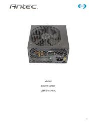
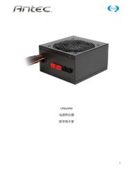
The Power Supply<br />
NSK 2400 comes with a 380 Watt universal input, active PFC, single 80mm fan<br />
cooled power supply compatible with the ATX12V version 2.01 specification and<br />
above. This includes dual 12V output rails that deliver safer and more reliable<br />
output to the system’s components, as well as higher energy efficiency, which<br />
reduces power consumption by up to 25% saving you money on your electricity<br />
bill. In addition we’ve included a variety of industrial-grade protective circuitry:<br />
OPP (over power protection), OVP (over voltage protection), UVP (under voltage<br />
protection), and SCP (short circuit protection).<br />
The power supply comes with a main power switch. Make sure you turn the<br />
switch to the ON ( I ) position before you boot up the computer for the first time.<br />
Normally, you won’t need to switch to the OFF (O) position, since the power supply<br />
includes a soft on/off feature. This lets you turn the computer on and off by<br />
using the soft switch on the computer case. If the computer crashes and you can’t<br />
shut it down using the soft switch, you can switch the main power to the OFF (O)<br />
position to clear the fault, then reboot.<br />
This power supply model features Power Factor Correction (PFC) circuitry in accordance<br />
with European standard regulation code EN61000-3-2. By altering the input<br />
current wave shape, PFC improves the power factor of the power supply. This<br />
results in increased energy efficiency, reduced heat loss, prolonged life for power<br />
distribution and consumption equipment, and improved output voltage stability.<br />
Together with the high efficiency design and the quiet 80mm fan, the power supply<br />
delivers not only a cleaner but also a quieter operating environment.<br />
Setting Up<br />
1. Place the case upright on a flat, stable surface.<br />
2. Remove the thumbscrews from the back of the top panel. Slide the panel towards<br />
the rear to remove it from the case.<br />
3. Inside the case you should see the power supply, some wiring with marked<br />
connectors (USB, PWR etc.), and installed I/O panel and a power cord.<br />
1
The Triple Chamber structure<br />
Upon opening the top panel, you will find the case is divided into three separate<br />
chambers – the power supply chamber, the motherboard chamber and the HDD<br />
chamber. This triple chamber structure isolates heat and noise from each section<br />
resulting in much quieter and cooler operation than a traditional desktop case.<br />
Installing the Motherboard<br />
This manual does not cover CPU, RAM, or expansion card installation. Please consult<br />
the motherboard manual for specific mounting instructions and troubleshooting.<br />
The motherboard is located inside the main chamber with two 120 mm TriCool<br />
fans preinstalled right next to the CPU.<br />
1. Lay the case down, with the open side facing up. The drive cages and power<br />
supply should be visible.<br />
2. Make sure you have the correct I/O panel for the motherboard. If the panel<br />
provided with the case isn’t suitable, please contact the motherboard manufacturer<br />
for the correct I/O panel.<br />
3. Line up the motherboard with the standoff holes, and remember which holes<br />
are lined up. Not all motherboards will match with all the provided holes; this is<br />
normal, and won’t affect functionally.<br />
4. Remove the motherboard by lifting it up.<br />
5. Screw the brass standoffs into the threaded holes that line up with the motherboard.<br />
Do not overtighten the standoffs. Some standoffs may be pre-installed<br />
for your convenience.<br />
6. Place the motherboard on the brass standoffs.<br />
7. Attach the motherboard to the standoffs with the provided Philips-head<br />
screws. The motherboard is now installed.<br />
Connecting the Power and LED<br />
The power supply conforms to the ATX12V Version 2.01 standard. If the motherboard<br />
has a 20-pin power receptacle, detach the 4-pin attachment on the 24-pin<br />
power connector, see pictures 1 and 2. Before you connect the power supply to<br />
any of the devices, please consult the appropriate user manuals for the motherboard<br />
and other peripherals.<br />
1. Connect the 24-pin Main Power Connector and the 4-<br />
pin or 8-pin connector to the motherboard as needed.<br />
If the motherboard uses a 20-pin connector; detach<br />
the 4-pin attachment on the 24-pin power connector<br />
(see pictures 1 and 2).<br />
2. Connect the Reset switch (labeled RESET SW) to the<br />
motherboard at the RST connector. Make sure the<br />
label always faces the front of the case.<br />
Picture 1 Picture 2<br />
For 24-pin<br />
motherboards<br />
For 20-pin<br />
motherboards<br />
3. Power LED (labeled POWER LED) connector is located behind the Reset<br />
connector.<br />
4. Power Switch (labeled POWER SW) connects to the PWR connector on the<br />
motherboard.<br />
5. Hard Drive LED (labeled H.D.D. LED) connects to the IDE connector.<br />
2
Connecting the USB Ports<br />
You will find a single 10-pin connector on a cable attached to the front USB ports.<br />
This is an Intel standard connector, which is keyed so that it can’t be accidentally,<br />
reversed as long as it is connected to a proper Intel standard motherboard header.<br />
Connect the 10-pin connector to the motherboard headers so that the blocked pin<br />
fits over the missing header pin.<br />
Note: Please check the motherboard manual for the USB header pin layout and<br />
make sure it matches the attached table. If it does not match this Intel standard,<br />
please call <strong>Antec</strong> customer support at (800) 22ANTEC (North America) or at<br />
+31 (0) 10 462-2060 (Europe) to buy a USB adapter. This adapter will allow you<br />
to connect the front USB to the motherboard on a pin-by-pin basis.<br />
Motherboard Pin Layout<br />
1 2<br />
9<br />
10<br />
Pin Signal Names Pin Signal Names<br />
1 USB Power 1 2 USB Power 2<br />
3 Negative Signal 1 4 Negative Signal 2<br />
5 Positive Signal 1 6 Positive Signal 2<br />
7 Ground 1 8 Ground 2<br />
9 Key (No Connection) 10 Empty Pin<br />
Connecting the Audio Ports<br />
There is an Intel standard 10-pin connector (with 7 individual wires with connectors)<br />
coming out from the front panel speaker and microphone connection. If the<br />
motherboard supports Intel’s standard onboard audio connector, you can plug in<br />
the 10-pin connector directly onto the board. For non-Intel standard audio connection,<br />
you need to plug the 7 individual connectors to the motherboard. See instruction<br />
below:<br />
Locate the internal audio connectors from the motherboard or sound card. Consult<br />
the motherboard or sound card manual for the pin-out positions.<br />
1. Microphone Signal Pin: Connect the MIC connector to this pin.<br />
2. Microphone Power: Connect the MIC-BIAS connector to this pin.<br />
3. Ground Pin: Connect the AUD GND connector to this pin.<br />
4. Front Right Speaker Out Pin: Connect the FPOUT-R connector to this pin.<br />
5. Front Left Speaker Out Pin: Connect the FPOUT-L connector to this pin.<br />
6. Rear Right Speaker Out Pin: Connect the RET-R connector to this pin.<br />
7. Rear Left Speaker Out Pin: Connect RET-L connector to this pin.<br />
3
Hard disk Drive Installation<br />
There is a hard disk drive bracket with soft silicone grommets inside the HDD<br />
chamber which can hold two hard drives.<br />
1. Remove the HDD bracket from the chamber by<br />
removing the four screws on top of it.<br />
2. Mount the left side of the hard drives (facing from<br />
the front of the hard drive) onto the drive bracket<br />
through the top silicone grommets with the special<br />
screws provided. (See picture 3) Note: Don’t overtighten<br />
the screws. Over-tightening the screws will<br />
reduce the vibration and noise-dampening ability of<br />
the silicone grommets.<br />
3. Place the HDD/bracket assembly back into the<br />
Picture 3<br />
case. Each hard drive should rest on two soft<br />
silicone grommets preinstalled at the bottom of the<br />
case. It is optional, but not necessary to attach the hard drives with screws<br />
through the bottom grommets.<br />
4. Fasten the bracket using the screws provided.<br />
5. Find a 4-pin Molex or a SATA connector on the power supply and connect it to<br />
the power connector on the device.<br />
5.25” Device Installation<br />
NSK 2400 incorporates a rapid-release Flip Up Drive Cage inside the power supply<br />
chamber for easy drive installation. The cage can hold two 5.25” devices.<br />
To install an external 5.25” device:<br />
1. Remove the flip-up drive cage.<br />
2. Remove the drive bay cover you intend to<br />
install the device.<br />
3. Insert the 5’25” device into the cage.<br />
Fasten the drive with the screws included.<br />
(See Picture 4)<br />
4. Find a 4-pin Molex or a SATA connector on<br />
the power supply and connect it to the power<br />
connector on the device.<br />
Picture 4<br />
Cooling System<br />
The 120 mm TriCool fans<br />
The NSK 2400 comes with two 120mm TriCool fans preinstalled. These fans sit<br />
right next to the CPU and are installed so that the air is blowing out of the case.<br />
Please leave at least 1” (2.5cm) between the right side of the case and anything<br />
that would block the exhaust from these fans. Failure to do so may cause the<br />
chamber or CPU to overheat.<br />
These fans have a three-speed switch that lets you choose between quiet, performance,<br />
or maximum cooling. (See specifications below.) Connect a large 4-pin<br />
connector from the power supply to the male 4-pin connector on the fan.<br />
Note: The default setting of the fans is Low. We recommend this speed to maximize<br />
quiet computing.<br />
4
Note regarding fan speed controllers: The minimum voltage to start the fan is<br />
5V. We recommend our users set the fan speed to High if the fan will be connected<br />
to a fan control device or to the Fan-Only connector found on some <strong>Antec</strong><br />
power supplies. A fan-control device regulates the fan speed by varying the voltage<br />
to it. The voltage may start as low as 4.5V to 5V. Connecting a TriCool set<br />
on Medium or Low to a fan-control device may result in the fan not being able<br />
to start. The already lowered voltage from the fan control device will be further<br />
reduced by the TriCool circuitry below 5V.<br />
Specifications:<br />
Size:<br />
120mm x 120mm x 25.4mm<br />
Rated Voltage:<br />
DC 12V<br />
Operating Voltage: 10.2V ~ 13.8V<br />
Speed<br />
Input<br />
Current<br />
Air Flow<br />
Static<br />
Pressure<br />
Acoustical<br />
Noise<br />
Input<br />
Power<br />
High<br />
2000 RPM<br />
0.24A<br />
(Max.)<br />
2.24 m³ / min<br />
(79 CFM)<br />
2.54 mm-H2O<br />
(0.10 inch-H2O)<br />
30 dBA 2.9 W<br />
Medium<br />
1600 RPM<br />
0.2A 1.59 m³ / min<br />
(56 CFM)<br />
1.53 mm-H2O<br />
(0.06 inch-H2O)<br />
28 dBA 2.4 W<br />
Low<br />
1200 RPM<br />
0.13A 1.1 m³ / min<br />
(39 CFM)<br />
0.92 mm-H2O<br />
(0.04 inch-H2O)<br />
25 dBA 1.6 W<br />
5
The Bottom Air Intake<br />
There are intake vents at the bottom of the case right under the HDD chamber.<br />
Fresh cool air will flow through the vents through the hard drives, and then flow<br />
into the motherboard chamber and exhaust by the two 120mm TriCool fans.<br />
Note: Do not place the <strong>NSK2400</strong> on a soft surface or over anything that will block<br />
the bottom air vents.<br />
The Upper Air Intake<br />
There are vents on the top panel above the PCI expansion slots. Fresh air will flow<br />
through it into the motherboard chamber to cool the hottest VGA card.<br />
Note: Do not place anything on top of the <strong>NSK2400</strong> that will block the top air<br />
vents.<br />
The Rear Air Intake<br />
There are vents right above the rear I/O panel and on the PCI expansion slot covers<br />
to bring in fresh air to help cool the CPU and VGA card.<br />
CPU Air Guide<br />
The CPU Air Guide, and rear air intake work together to provide fresh air to the<br />
CPU cooler to enhance the CPU cooling. The CPU Air Guide consists of several<br />
sections which can be adjusted to best suit each individual motherboard CPU position.<br />
The Power Supply Air Intake<br />
There are vents on the left side of the case to bring fresh air into the power supply<br />
chamber to cool the power supply.<br />
Note: Please leave at least 1” (2.5cm) between the left side of the case and<br />
anything that could block airflow to the power supply. This is required so that the<br />
power supply will have sufficient cooling.<br />
6
<strong>Antec</strong>, Inc.<br />
47900 Fremont Blvd.<br />
Fremont, CA 94538<br />
USA<br />
tel: 510-770-1200<br />
fax: 510-770-1288<br />
<strong>Antec</strong> Europe B.V.<br />
Sydneystraat 33<br />
3047 BP Rotterdam<br />
The Netherlands<br />
tel: +31 (0) 10 462-2060<br />
fax: +31 (0) 10 437-1752<br />
Technical Support:<br />
US & Canada<br />
1-800-22ANTEC<br />
customersupport@antec.com<br />
Europe<br />
+31 (0) 10 462-2060<br />
europe.techsupport@antec.com<br />
www.antec.com<br />
© Copyright 2006 <strong>Antec</strong>, Inc. All rights reserved.<br />
All trademarks are the property of their respective owners.<br />
Reproduction in whole or in part without written permission is prohibited.<br />
Printed in China.<br />
Version 1.0.1 02/16/2006