Boeing-Stearman Kaydet PT13/17 US Airforce / Navy Primary Trainer
Boeing-Stearman Kaydet PT13/17 US Airforce / Navy Primary Trainer
Boeing-Stearman Kaydet PT13/17 US Airforce / Navy Primary Trainer

You also want an ePaper? Increase the reach of your titles
YUMPU automatically turns print PDFs into web optimized ePapers that Google loves.
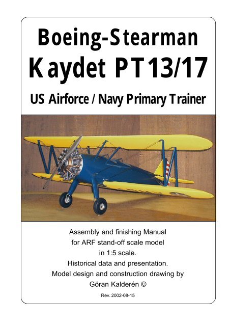
<strong>Boeing</strong>-<strong>Stearman</strong><br />
<strong>Kaydet</strong> <strong>PT13</strong>/<strong>17</strong><br />
<strong>US</strong> <strong>Airforce</strong> / <strong>Navy</strong> <strong>Primary</strong> <strong>Trainer</strong><br />
Assembly and finishing Manual<br />
for ARF stand-off scale model<br />
in 1:5 scale.<br />
Historical data and presentation.<br />
Model design and construction drawing by<br />
Göran Kalderén ©<br />
Rev. 2002-08-15
<strong>Stearman</strong> <strong>Kaydet</strong> PT<strong>17</strong> ARF 2
<strong>Stearman</strong> <strong>Kaydet</strong> PT<strong>17</strong> ARF 3
<strong>Stearman</strong> <strong>Kaydet</strong> PT<strong>17</strong> ARF 4
Boieng <strong>Stearman</strong> PT-<strong>17</strong> ’<strong>Kaydet</strong>’<br />
Nicknamed the ”Yellow Peril” thanks to its<br />
somewhat tricky ground handling characteristics, the<br />
<strong>Stearman</strong> is one of the most easily recognized aircraft.<br />
Its simple construction, rugged dependability and<br />
nimble handling made the <strong>Stearman</strong> much loved by<br />
those who flew and trained on it. The <strong>Stearman</strong> <strong>Kaydet</strong>,<br />
as it was officially named, was the only American aircraft<br />
used during World War II that was completely<br />
standardized for both Army and <strong>Navy</strong> use as the PT<br />
13D (Army) and N255 (<strong>Navy</strong>). Sold by the thousands<br />
after World War II, the <strong>Stearman</strong> has had a long and<br />
full career as a trainer, crop duster and air show performer.<br />
The famed <strong>Stearman</strong> Model 75 has its roots<br />
in the earlier Model 70, which was chosen in 1934 as<br />
the U.S. <strong>Navy</strong>’s primary trainer. At a time when biplanes<br />
were becoming a thing of the past, the Model<br />
70 offered the fledgling pilot a steady and sturdy steed.<br />
Designed and built in only 60 days, the prototype Model<br />
70 could withstand load factors much higher than were<br />
expected to occur in normal flight training. The U.S.<br />
Army and <strong>Navy</strong> tested the prototype in 1934. At the<br />
conclusion of these tests, the <strong>Navy</strong> ordered the aircraft<br />
while the Army decided to wait for the introduction<br />
of the improved Model 75 appearing in 1936. Over<br />
the next decade, the Armydecided to wait for the introduction<br />
of the improved Model 75 appearing in 1936.<br />
Over the next decade, the Army received nearly 8,500<br />
<strong>Stearman</strong>s in five different variants. The difference<br />
among these versions were the engines fitted; <strong>Kaydet</strong>s<br />
were fitted with Lycoming (PT 13), Continental (PT<br />
<strong>17</strong>) or Jacobs (PT 18) radial engines. The U.S. <strong>Navy</strong><br />
took delivery of their first <strong>Stearman</strong> (called the NS-1 )<br />
in 1934. Powered with the obsolete but readily available<br />
Wright R-790-8 engine, the NS-1 proved its worth<br />
as a primary trainer. The <strong>Navy</strong> purchased several thousand<br />
of an improved model, the N2S. The N2S was<br />
built in five sub variants, each variant being equipped<br />
with a different model engine. Additionally, the Canadian<br />
armed forces took delivery of 300 PT 27s, a winterized<br />
version of the PT <strong>17</strong>.<br />
A later, more powerful version of the <strong>Stearman</strong>,<br />
the Model 76, was purchased by Argentina, Brazil and<br />
the Philippines.<br />
<strong>Stearman</strong> <strong>Kaydet</strong> PT<strong>17</strong> ARF 5
<strong>Stearman</strong> PT-<strong>17</strong> <strong>Kaydet</strong><br />
Length: 25' 7.62 M<br />
Height: 9' 2" 2.79 M<br />
Wingspan: 32' 2" 9.80 M<br />
<strong>Stearman</strong> <strong>Kaydet</strong> PT<strong>17</strong> ARF 6<br />
Wingarea: 297.00 Sq Ft 27.59 Sq M<br />
Empty Weight: 1936.00 lbs 878.00 Kg<br />
Gross Weight: 27<strong>17</strong>.00 lbs 1232.00 Kg<br />
Powerplant: Continental R-670-5, 220 hp
The Model<br />
We have chosen the scale of 1:5 rendering<br />
a model size that i easy to fly but also relatively<br />
easy to transport. Both the upper and the lower<br />
wing panels can be removed for transportation<br />
which gives very limited requirement for<br />
transportation size. With a .1.20 4-stroke engine<br />
the airplane is capable of most of the manoeuvers<br />
in the book but still as docile as you can demand<br />
from a n advanced trainer.<br />
The finished model is painted in 1939 livery<br />
and further detailing can be made as per<br />
documentation.<br />
Specifications:<br />
Wingspan cm 193<br />
Wingspan inches 77.2<br />
Length cm 149<br />
Length inches 59.6<br />
Weight grams 6600<br />
Weight Lb/oz 14lb. 8 oz.<br />
Wing surface dm² 118 dm²<br />
Wing surface Sq.inch 1888 sq”<br />
Wing load g/dm² 56 g/dm²<br />
Wing load oz/Sq’ 24 oz/sq’<br />
Engine 2-cycle .60 - .90<br />
Engine 4-cycle .90 - 1.20<br />
C/G fr. Lead.edge upper wing 15cm / 6”<br />
Covering and finish<br />
The model is covered and painted from the<br />
factory. Where the original had aluminum covering<br />
panels, the model has the same. This also means<br />
excellent acces to the various compartments in<br />
the fuselage when installing or servicing the radio<br />
equipment. When you have made changes in the<br />
fire wall and adapted the dummy engine to fit in<br />
front of the engine, you will have to cover the open<br />
areas with fuel proof paint.<br />
Installation of engine.<br />
Our prototype was tried with an OS 1.20 FS<br />
surcharge 4-stroke which gave more than ample<br />
thrust. The engine mounts have been installed<br />
for this size of engine and in an upright position<br />
for several reasons.<br />
The need for adequate cooling. The access<br />
to the glow plug easily and finally to get the<br />
carburator in line with the center of the tank.<br />
1. Drill the holed for the engine in the ½"<br />
plywood ingine mount. Install blind nuts underside<br />
of the plywood aligned with the holes<br />
2. Drill the holes from the tank to the<br />
carburator, pressure tap and the filling cap.<br />
3. Install the engine and connect the throttle<br />
servo.<br />
No side or down thrust is deemed necessary. You<br />
can use an flexible exhaust manifold to lead the<br />
exhaust out under the center bottom panel to give<br />
a better apperance.<br />
Installation of servos, tank, battery and<br />
receiver.<br />
The aileron servo is installed in the cockpit<br />
flooring. The elevator servo and the rudder<br />
servo are also installed in the cockpit flooring.<br />
The trottle servo is installed behind the<br />
engine as well as the tank, booth on the<br />
engineboard.<br />
Battery pack and receiver are positioned<br />
in the upper part of the tray.<br />
The switch can be mounted on the front<br />
cockpit instrument panel.<br />
1. Attach a ball link head to joystick and<br />
rudder bar in the appropriate holes. You may have<br />
to enlarge the holes to take the screw from the<br />
ball link (Dubro #189 set of 2).<br />
2. Install the servos for rudder and elevator<br />
and temporarily connect the servo arms to the<br />
ball links. Deflection for elevator is 20° up and<br />
down and for rudder 30° right and left..<br />
3. Install and connect the throttle servo in<br />
the fashion you prefer.<br />
4. Install the tank in the available space at<br />
the right side next to the rudder and throttle<br />
servos..<br />
5. Install the aileron servo in the bulkhead.<br />
The aileron connecting rods attaches to the servo<br />
arm. Deflection of the ailerons should be 20° up<br />
and down. The servo arm should be fashioned to<br />
take 2 clevices approx 1/8" apart.<br />
6. Install the radio switch on the dash board.<br />
7. Place the receiver in the upper part of the<br />
tray and the battery pack in front of the lower<br />
firewall, wrapped in foam rubber and secured with<br />
rubber bands.<br />
Assembly of the PT<strong>17</strong><br />
All parts have been assembled at the factory<br />
and only disassembled for transportation.<br />
Rudder wires and elevator pushrod are<br />
factory adjusted but may need some tensioning<br />
adjustment after a while. Aileron bellcranks are<br />
permanently adjusted to the connecting rod.<br />
Assembly of the tail unit<br />
See detail drawing.<br />
1. Attach horizontal tail(3) to fuselage using 3 pcs<br />
4 mm nylon countersunk screws. Make sure that<br />
stabilizer is flat against fuselage.<br />
2. connect the elevator control rod to the elevator<br />
horn.<br />
3. Insert vertical fin and secure to tailpost bracket<br />
and front of stabilizer. Attach rudder on to the fin<br />
with hinge pins.<br />
4. Secure the assembly with screws to the<br />
stabilizer and to the tailpost. Attach the top<br />
stabilizer fairing and secure with screws.<br />
5. Attach fin and stabilixer support wires to top of<br />
fin using 2 mm screw and nut (from top side of<br />
<strong>Stearman</strong> <strong>Kaydet</strong> PT<strong>17</strong> ARF 7
<strong>Stearman</strong> <strong>Kaydet</strong> PT<strong>17</strong> ARF 8
<strong>Stearman</strong> <strong>Kaydet</strong> PT<strong>17</strong> ARF 9
stabilizer to top of fin).<br />
6. Secure and tighten all screws and nuts.<br />
Check the action of elevator and rudder. The<br />
elevator is actuated with the joy-stick and the<br />
rudder with the rudder bar.<br />
Assembly of wing panels<br />
1. Push the lower wing halves into the holes<br />
in the fuselage.<br />
2. Attach the upper wing center section using<br />
the 4 Allen 6-32 screws supplied (note that the<br />
front screws are longer and the rear screws<br />
shorter). Attach ball links or clevices to the aileron<br />
push rods. Connect the aileron push rods to the<br />
servo in the fuselage.. Check the movement of<br />
the ailerons. 20° up and 15° down throw.<br />
3. Install the interplane struts. Connect the<br />
flying wires and the landing wires. Attach the flying<br />
wires in place. Attach the landing wires in<br />
place. Adjust if necessary, the rear lower<br />
incidence adjustment screw and the fasten this<br />
assembly to the bracket on the lower wing using<br />
2 mm screw and locknut.<br />
Should you need to replace a wire, use the<br />
attachment method indicated in the picture. When<br />
crimping the cerulet (sleeve) use a flat plier, press<br />
firmly and don't cut through the wire.<br />
Landing gear<br />
Install the wheel shafts and secure with the<br />
Allen socket locking screws. The landing gear is<br />
completely built up with oleo spring action and is<br />
<strong>Stearman</strong> <strong>Kaydet</strong> PT<strong>17</strong> ARF 10<br />
an integrated part of the fuselage. The wheels<br />
are secured with locking rings and the wheel caps<br />
are pushed onto the wheel hubs.<br />
Balancing<br />
The center of gravity / balancing point should be<br />
approx. 15 cm (6") measured from the leading<br />
edge on the upper wing. Make adjustments if<br />
necessary.<br />
Flying<br />
The prototype was flown with a OS 1.20<br />
4-stroke FS which provides ample thrust. Let the<br />
engine swing a 18x6 propeller if possible. This<br />
gives better thrust outside the big dummy engine<br />
and reduces sound to a more realistic level.<br />
Flying characteristics are very forgiving<br />
and will fly hapily on half trottle. Set the elevator<br />
at zero angle for the first flight but be prepared<br />
to give down elevator if the model climbs out too<br />
steep. During the initial take off run you have to<br />
compensate for the torque with right rudder but<br />
as the speed builds up the rudder is returned to<br />
neutrual. This model should fly of the ground and<br />
not be pulled.<br />
The landing approach can be rather<br />
steep as per prototype but the flare out needs<br />
almost full up elevator. Maintain directional<br />
heading and remember, the aircraft has a<br />
stearable tailwheel.<br />
Happy landings!
The tailwheel is<br />
coupled to the<br />
rudder bar and has<br />
50% throw of the<br />
rudder<br />
Rudder and elevator servos in the flooring<br />
of front cockpit<br />
Aileron servo in the<br />
flooring of rear<br />
cockpit. Note the<br />
servo arm with 2<br />
attachment point<br />
for the clevices of<br />
the aileron push<br />
rods.<br />
The OS 1.2 engine blends nicely with the<br />
dummy engine<br />
Push rods from the servos attach to the<br />
rudder bar and the control column.<br />
<strong>Stearman</strong> <strong>Kaydet</strong> PT<strong>17</strong> ARF 11
What is in the box:<br />
The ARF kit contains the parts shown in the picture.<br />
All the parts are covered and painted. All the rigging<br />
5<br />
4<br />
3<br />
2<br />
1. Fuselage with wing cabane<br />
2. Landing gear<br />
3. Scale wheels<br />
4. Dummy engine with mount<br />
5. Scale propeller<br />
6. Tail wheel assy (stearable).<br />
7. Fin with tailfairing / rudder<br />
8. Stabilizer / elevator<br />
K&W<br />
11<br />
9<br />
<strong>Stearman</strong> <strong>Kaydet</strong> PT<strong>17</strong> ARF 12<br />
10<br />
Model<br />
Airplanes Inc.<br />
1<br />
wires are supplied in the correct lengths and need<br />
only to be clipped to their positions.<br />
9. Upper wing panels<br />
10. Lower wing panels<br />
11. Interplane struts<br />
12. Wires, turnbuckles and hardware for assembly<br />
(not shown)<br />
13. Assembly manual with scale<br />
documentation<br />
P.O.Box 1229, Cebu City Centrl. Postoffice<br />
Cebu City 6000, Philippines<br />
Visiting address:<br />
3343 Gun-Ob, Kinalumsan,<br />
Lapu-Lapu City 6015, PHILIPPINES<br />
Phone +63 32-340 0772, Cellular +63 9<strong>17</strong>-3200 985<br />
Telefax +63 32-340 7131, E-mail: kwmairpl@gsilink.com<br />
Website http://www.kwmairpl.com.ph<br />
8<br />
6<br />
13<br />
7